
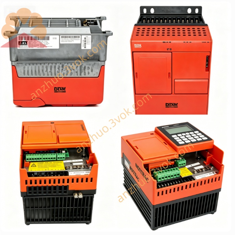
SEW MKS51A015-503 MOVIDRIVE Compact Drive Inverter
Description
1. Product Overview
2. Model Code Explanation
MKS51A: MOVIDYN compact servo drive series
015: Rated output power 15 kW
503: 3‑phase 380–500 V AC, standard version
3. Technical Specifications
3.1 Electrical Parameters
Input Voltage: 3×380–500 V AC (‑10% / +10%), 50/60 Hz
Rated Output Current: 13.5 A
Rated Output Power: 15 kW (continuous mechanical)
Control Voltage: 24 V DC
Output Frequency: 0–400 Hz
Control Modes: Speed, torque, position control
Communication: Ethernet (Modbus/TCP), RS‑485; optional PROFIBUS/PROFINET
Safety: Optional STO (Safe Torque Off), PL d / SIL 2
Digital I/O: 8 inputs / 4 outputs (programmable)
3.2 Mechanical & Environmental
Protection Class: IP20 (cabinet mounting only)
Cooling: Natural convection + temperature‑controlled fan
Mounting: 35 mm DIN rail or wall‑mount
Dimensions (W×H×D): Approx. 130 × 300 × 220 mm
Weight: Approx. 6.8 kg
Operating Temperature: 0 °C to +45 °C
Storage Temperature: -20 °C to +60 °C
4. Main Features
Compact integrated design saves cabinet space.
Advanced vector control ensures smooth low‑speed operation and high positioning accuracy.
LED status indicators (power, run, fault); local buttons for start/stop/reset.
Firmware update via USB or fieldbus.
Flexible programmable I/O for diverse control tasks.
Standard industrial communication for easy PLC/host connection.
5. Typical Applications
Conveying and packaging machinery
Machine tools and material handling
Automated assembly lines and robotic systems
6. Installation & Wiring
6.1 Mechanical Installation
Mount on a rigid, vibration‑free DIN rail or wall.
Maintain ≥50 mm clearance around the drive for cooling.
Tighten mounting screws to 2.5 Nm.
6.2 Electrical Wiring
Power (L1/L2/L3/PE): 3×380–500 V AC, reliable protective earth.
Motor (U/V/W/PE): Shielded cable to servo motor.
Communication: Ethernet/RS‑485 to controller or PC.
STO (Optional): 24 V DC safety signal to STO terminals.
6.3 EMC Guidelines
Use shielded cables for power, motor, and signal lines; ground shields at both ends.
Separate power and signal cables by ≥20 cm to reduce interference.
7. Commissioning & Operation
Verify all wiring, connections, and insulation before power‑on.
Apply main power; green LED indicates standby.
Configure parameters, motor data, and communication via SEW MOVITOOLS®.
Test run at low speed; check for noise/vibration. Gradually increase to rated speed/load.
Monitor operating temperature; keep <70 °C.
8. Maintenance
Inspect every 6 months.
Clean dust from vents and fan regularly.
Check terminal tightness and cable insulation.
Verify cooling fan operation.
9. Fault Diagnosis
F01 Overcurrent: Short circuit, overload, or motor fault. Check wiring/load.
F02 Overvoltage: Supply surge or regenerative voltage.
F03 Overtemperature: Blocked ventilation or fan failure.
F04 Comm Error: Cable damage or address mismatch.
10. Storage & Disposal
Store in a dry, clean environment within temperature limits; keep original packaging.
Dispose per local WEEE regulations; recycle metal, plastic, and electronics separately.
Get a Quote