
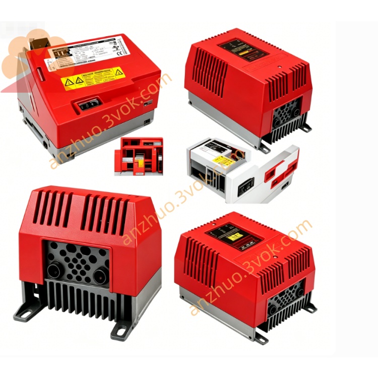
SEW MDX61B0750-503-4-00 MOVIDRIVE B Servo Inverter
Description
1. General Description
2. Model Code Explanation
MDX61B: MOVIDRIVE B series, with dual expansion slots for encoder and fieldbus modules
0750: Rated power 75 kW (Constant Torque)
503: 3-phase 380–500 V AC, no integrated EMC filter
4: Integrated brake chopper, supports four-quadrant regenerative operation
00: Standard non-coated PCB
3. Technical Specifications
3.1 Electrical Parameters
Input Voltage: 3×380–500 V AC (-15% ~ +10%), 50/60 Hz
Rated Input Current: 117 A (at 400 V)
Rated Output Power: 75 kW (CT)
Rated Output Current: 130 A
Apparent Power: 91 kVA
Output Frequency Range: 0–400 Hz
Control Modes: V/f control, VFC vector control, CFC closed-loop vector control, servo control
Overload Capability: 150% rated current for 60 s; 175% rated current for 2 s
Switching Frequency: 4 kHz, 8 kHz, 12 kHz, 16 kHz (adjustable)
Safety Function: STO (Safe Torque Off), compliant with PL d / SIL 2
3.2 Mechanical & Environmental Parameters
Protection Class: IP20 (cabinet installation only)
Dimensions (W × H × D): 280 × 610 × 330 mm
Weight: Approximately 35 kg
Operating Temperature: 0 °C to +40 °C. Power derating is required when temperature exceeds 40 °C.
Storage Temperature: -25 °C to +70 °C
Altitude: No power derating below 1000 m; derate 1% per additional 100 m above 1000 m
Certifications: CE, UL, RoHS, EAC
4. Version Comparison
00: Standard non-coated PCB, for clean and dry environments
0T: Conformal coated PCB, for humid, dusty or mildly corrosive environments
50: Special factory customized version
5. Main Features
Four-quadrant operation with built-in brake chopper realizes regenerative braking and energy recovery.
External EMC filter must be installed to meet electromagnetic compatibility requirements.
Modular design allows expansion with optional encoder and various fieldbus modules.
Integrated IPOSplus® motion system supports positioning, electronic gearing and master-slave synchronization.
Standard PCB design for reliable operation under normal industrial conditions.
STO safety function complies with international machine safety standards.
6. Installation & Wiring
Mounting Method: Vertical installation inside control cabinet.
Ventilation Clearance: Minimum 100 mm space at top and bottom, 50 mm on both sides.
Main Terminals:
X1: Mains connection (L1, L2, L3, PE)
X2: Motor connection (U, V, W, PE)
X4: DC link terminals for external brake resistor
X11: Analog input (0–10 V / 4–20 mA)
X13: 24 V DC digital inputs and outputs
X15 / X16: Encoder interfaces
7. Operation & Commissioning
Local Operation: DBG60B handheld keypad for parameter setting, manual operation and fault checking.
PC Commissioning: MOVITOOLS® MotionStudio for program editing, real-time monitoring and fault diagnosis.
Operating Modes: Jog mode, reference homing, positioning mode, synchronous operation.
8. Safety Instructions
Installation, wiring and commissioning shall only be performed by qualified electrical personnel.
High residual voltage remains inside the drive after power-off. Wait at least 5 minutes for full capacitor discharge before touching internal terminals.
Use shielded cables for motor and signal wiring, and match with a qualified external EMC filter.
9. Maintenance & Troubleshooting
Routine Maintenance: Regularly inspect cable connections and ventilation passages. Remove dust with dry compressed air.
Typical Faults: Overcurrent (OC), Overvoltage (OV), Overtemperature (OT), Encoder Error. Fault codes can be checked via keypad or supporting software.
10. Typical Applications
Conveyors, cranes and hoists
Packaging, textile and woodworking machinery
Large fans, pumps and process production equipment
General industrial sites with clean and dry operating conditions
Get a Quote