
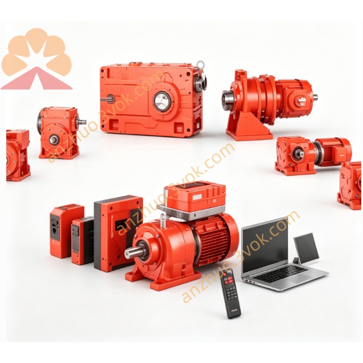
SEW MDX61B0012-5A3 MOVIDRIVE B Drive
Description
1. General Information
1.1 Product Overview
1.2 Model Decoding
MDX61B: High-performance drive series with two option slots (encoder + fieldbus).
0012: Rated motor power = 1.5 kW.
5A3: 5 = 380–500 V AC; A = Class C2 EMC filter; 3 = three-phase input.
(suffix omitted): Standard version (non-coated PCB, basic motion functions).
1.3 Safety Symbols
DANGER: High voltage inside—risk of electric shock.
WARNING: Potential personal injury or equipment damage.
CAUTION: Minor injury or component fault risk.
NOTE: Important operation/maintenance tips.
1.4 Intended Use
1.5 Warranty
2. Technical Specifications
2.1 Electrical Data (3 × 380–500 V AC, 50/60 Hz)
Rated input current: 3.6 A
Rated output power: 1.5 kW
Rated output current: 4.0 A
Apparent power: 2.6 kVA
Output frequency: 0–599 Hz
Overload: 200% / 60 s; 175% / 2 s
PWM carrier: 4 kHz (default); 8/16 kHz selectable
Brake chopper: Integrated (external resistor ≥68 Ω required)
EMC filter: Class C2 (EN 61800-3)
2.2 Mechanical & Environmental
Protection class: IP20 (install in control cabinet)
Dimensions (W×H×D): 105 × 260 × 95 mm
Weight: ~3.1 kg
Cooling: Temperature-controlled forced air
Operating temp: 0 °C to +50 °C (derate >40 °C)
Storage temp: −25 °C to +70 °C
Altitude: ≤1000 m (no derating); >1000 m: −1% per 100 m
PCB: Standard (non-conformal coated)
2.3 Control Modes & Interfaces
VFC (V/f): Open-loop, general speed control.
CFC: Closed-loop vector, high torque/accuracy.
Servo: With encoder, for permanent magnet motors.
IPOSplus®: Basic positioning, electronic cam, master-slave sync, flying restart, DC braking.
PID controller: For flow/pressure closed-loop control.
Analog inputs: ±10 V, 4–20 mA
Digital inputs: 6 × 24 V DC isolated
Digital outputs: 2 × transistor, 1 × relay
Motor thermistor input (PTC)
Communication: SBus, RS485 (Modbus RTU)
Option slots: Encoder (e.g., DEH11B) + fieldbus (e.g., PROFINET, CANopen)
2.4 Safety & Protection
STO (Safe Torque Off): PL d compliant.
Protection: Overcurrent, overvoltage, undervoltage, overtemperature, ground fault, short circuit, motor overtemperature (PTC).
Fault response: Alarm + safe stop; fault code displayed on 7-segment LED.
3. Installation
3.1 Unpacking & Inspection
Check for physical damage (dents, scratches).
Verify model: MDX61B0012-5A3.
Confirm accessories: Mounting screws, terminal covers, manual.
3.2 Mounting
Install vertically in clean, dry, ventilated cabinet.
Clearance: 100 mm top/bottom for airfloweero.
Avoid direct sunlight, heat sources, corrosive gases.
Fix with M4 screws; torque 1.2–1.5 Nm.
3.3 Wiring
L1/L2/L3: 3 × 380–500 V AC input
PE: Protective earth
U/V/W: Motor output
+R/−R: External brake resistor
X10: Digital inputs (24 V DC)
X11: Digital outputs
X12: Analog inputs
X13: PTC thermistor
X14: Encoder (option)
X15: SBus/RS485
X17: STO safety input
Separate power and signal cables (≥20 cm).
Use shielded cables for signals; ground shields at both ends.
Torque terminals to 0.8–1.0 Nm.
Recheck all connections before power-on.
4. Commissioning
4.1 Pre-Start Check
All wiring correct and tight.
Terminal covers installed.
No foreign objects in cabinet.
Ambient conditions within limits.
4.2 Basic Parameter Setup (via DBG60B keypad or MOVITOOLS®)
Set motor data (nameplate):
Rated power: 1.5 kW
Rated voltage: 400 V
Rated current: ~4.0 A
Rated frequency: 50 Hz
Rated speed: 1450 rpm
Select control mode (VFC/CFC/Servo).
Set frequency limits: Min 0 Hz, Max 50 Hz (default).
Accel/decel time: 5 s (default).
Configure I/O functions (e.g., start/stop, speed reference).
Run auto-tuning (CFC/Servo mode).
4.3 Operation
Jog mode: Test motor rotation and speed.
No-load run: Check for noise, vibration, overheating.
Loaded run: Gradually apply load; monitor current/temp.
Long-term: Check parameters periodically; clean fan/filters.
5. Maintenance & Troubleshooting
5.1 Maintenance
Power off and wait 10 min before maintenance (capacitor discharge).
Clean dust from heat sink/fan every 3–6 months.
Check terminal tightness and cable insulation.
Replace damaged cables immediately.
5.2 Common Faults
Overvoltage (F01): High supply voltage; regenerative load.
Undervoltage (F02): Low supply; loose wiring.
Overcurrent (F03): Short circuit; motor overload.
Overtemp (F04): Dirty fan; high ambient temp.
Motor overtemp (F05): PTC trip; motor overload.
Ground fault (F06): Cable/motor insulation failure.
6. Compliance & Certifications
CE (EN 61800-3, EN 60204-1)
UL 508C, CSA
RoHS compliant
7. Version Notes
Standard (00): Non-coated PCB, basic motion, for clean/dry environments.
0T: Conformal coated PCB, advanced motion (electronic cam, multi-axis sync), for harsh environments (dust/moisture).
Get a Quote