
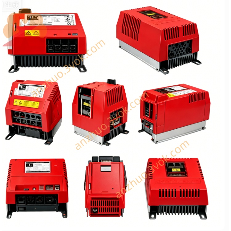
SEW MDX61B0008-5A3-4-0T MOVIDRIVE B Servo Drive
MDX61B0008-5A3-4-0T is a high-performance variable frequency drive manufactured by SEW-EURODRIVE under the MOVIDRIVE MDX61B series. It is specially configured to drive three-phase motors with a rated power of 0.75 kW. This unit supports closed-loop vector control and servo control functions, and it is equipped with the extended IPOSplus® motion system to realize electronic cam operation and master-slave synchronization. The printed circuit board adopts conformal coating, which enables the drive to work reliably in harsh industrial environments with dust and moisture.
Description
1.1 Product Overview
MDX61B0008-5A3-4-0T is a high-performance variable frequency drive manufactured by SEW-EURODRIVE under the MOVIDRIVE MDX61B series. It is specially configured to drive three-phase motors with a rated power of 0.75 kW. This unit supports closed-loop vector control and servo control functions, and it is equipped with the extended IPOSplus® motion system to realize electronic cam operation and master-slave synchronization. The printed circuit board adopts conformal coating, which enables the drive to work reliably in harsh industrial environments with dust and moisture.
1.2 Model Explanation
MDX61B represents the high-performance drive series fitted with two expansion slots for optional modules. The code 0008 stands for the rated motor power of 0.75 kW. 5A3 indicates the drive is designed for three-phase 380 V to 500 V AC power supply and comes with an integrated Class C2 EMC filter. The digit 4 means a built-in brake chopper is equipped to support four-quadrant operation. The suffix 0T refers to the application version with conformal coated PCB and full set of extended motion control functions.
1.3 Safety Markings
DANGER indicates high voltage inside the unit which may cause electric shock. WARNING reminds users of potential personal injury or equipment damage. CAUTION is used for possible minor injuries or component faults. NOTE highlights important tips for daily operation and maintenance.
1.4 Intended Application
This drive is used to regulate the speed and operation of three-phase asynchronous and synchronous motors with 0.75 kW power rating. It is widely applied in industrial automation scenarios including conveying systems, packaging machines, material handling equipment, water pumps and fans. Thanks to the coated PCB, it can operate stably in dusty and humid working conditions. It is also ideal for equipment requiring precise positioning, electronic cam movement and synchronous linkage between multiple axes.
1.5 Warranty Statement
The product warranty will remain valid only if all installation, commissioning and operation work strictly follows the requirements stated in this manual and official guidelines of SEW-EURODRIVE. Any damage caused by improper use, long-term overload operation or unauthorized disassembly and modification will void the warranty service.
2. Technical Specifications
2.1 Electrical Parameters
The drive accepts three-phase AC input voltage ranging from 380 V to 500 V with a voltage tolerance of minus 10 percent to plus 10 percent, and the applicable power frequency is 50 Hz or 60 Hz. The rated input current is 2.2 A. The rated output power reaches 0.75 kW with an apparent power of 1.6 kVA and rated output current of 2.4 A. The adjustable output frequency ranges from 0 Hz to 599 Hz. In terms of overload capacity, it can sustain 200 percent of rated current for 60 seconds and 175 percent of rated current for 2 seconds. The PWM carrier frequency is set to 4 kHz by default, and users can switch to 8 kHz or 16 kHz as needed. A brake chopper is integrated inside the drive, and an external braking resistor with resistance no less than 68 ohms must be connected for normal braking performance. The built-in EMC filter complies with Class C2 standard specified in EN 61800-3.
2.2 Mechanical and Environmental Requirements
The protection class of the drive is IP20, so it must be installed inside a closed control cabinet. The overall dimension is 105 millimeters in width, 260 millimeters in height and 95 millimeters in depth, and the total weight is approximately 3.1 kilograms. It adopts temperature-controlled forced air cooling to guarantee stable heat dissipation. The allowable operating ambient temperature is from 0 degrees Celsius to 50 degrees Celsius. When the ambient temperature exceeds 40 degrees Celsius, power derating is required for continuous operation. The storage temperature ranges from minus 25 degrees Celsius to 70 degrees Celsius. The internal PCB is processed with conformal coating to resist moisture, dust and slight corrosive gas. For installation altitude within 1000 meters, no derating is needed. If the installation height is above 1000 meters, derate the power by 1 percent for every additional 100 meters.
2.3 Control Functions and Interfaces
This drive provides three mainstream control modes. VFC open-loop volts-per-hertz control is suitable for ordinary speed regulation demands. CFC closed-loop vector control delivers high torque output and accurate speed control. Servo control mode is available when matched with an encoder, for driving permanent magnet synchronous motors.
The extended IPOSplus® system supports multiple advanced motion functions, including electronic cam operation, master-slave synchronous running, automatic flying restart and DC braking. A built-in PID controller is also provided to realize closed-loop regulation for flow, pressure and other process parameters. It also supports advanced single-axis positioning and logic sequence control. Two reserved expansion slots allow users to install encoder modules and various fieldbus communication cards.
For signal interfaces, the drive is equipped with analog input terminals that support plus or minus 10 V and 4 to 20 mA signals. It has multiple 24 V DC isolated digital input channels, as well as programmable digital outputs composed of transistor outputs and one relay output. A dedicated interface is reserved for connecting motor thermistor sensors to monitor motor temperature in real time. Standard communication interfaces include SBus system bus and RS485 bus which supports Modbus RTU protocol. Users can expand communication functions such as PROFINET, EtherNet/IP and CANopen by installing optional modules to realize data interaction with upper control systems.
2.4 Safety and Protection Functions
The drive is fitted with STO Safe Torque Off function which meets PL d safety standard. It integrates comprehensive protection mechanisms to prevent equipment failure. It can detect overcurrent, overvoltage, undervoltage, internal overtemperature, ground fault and short circuit. It also monitors motor overtemperature through external thermistor signals. Once any fault is detected, the drive will immediately send out alarm signals and execute safe stop actions. The running status and specific fault codes can be checked via the onboard display panel.
3. Installation Guide
3.1 Unpacking and Inspection
Take the drive out of the packaging materials carefully. Conduct a visual inspection to check for surface dents, scratches or loose internal parts. Confirm the model number is MDX61B0008-5A3-4-0T to ensure the received product matches the order. Check and count all attached accessories such as mounting screws, terminal protective covers and paper manuals.
3.2 Mounting Requirements and Steps
The drive shall be mounted in a clean, dry and well-ventilated control cabinet. Keep a clearance of 100 millimeters above and below the drive to ensure smooth air circulation for heat dissipation. Do not install the unit near direct sunlight, heat sources or areas filled with corrosive gas.
Mark the installation hole positions according to the product dimension, and fix the drive vertically with M4 screws. The recommended screw tightening torque is between 1.2 Nm and 1.5 Nm. Keep the drive in vertical state during installation to ensure the built-in fan works normally.
3.3 Wiring Instructions
Classify and connect all terminals in accordance with the terminal definition. Connect three-phase AC power supply to L1, L2 and L3 terminals of the power input terminal block, and connect the PE terminal to protective ground reliably. Connect the three-phase motor cable to U, V and W terminals of the motor output terminal block, and complete the ground connection as well.
Link the external braking resistor to the +R and -R terminals of the brake interface, and connect the corresponding ground terminal. Wire digital inputs, digital outputs and motor thermistor to the matched terminals respectively. Connect analog signal lines to analog input terminals for speed or reference signal input. Complete the wiring of SBus, RS485 communication lines and STO safety signal lines according to actual control demands. After all wiring is finished, check every connection again to make sure no loose wiring or wrong connection exists.
4. Commissioning and Operation
4.1 Pre-start Check
Before powering on, confirm all wiring is correct and firm. Check that the protective covers of all terminal blocks are installed properly. Verify the ambient environment and installation status meet the operating requirements. Confirm no foreign objects are left inside the cabinet or around the drive.
4.2 Basic Parameter Setting
Power on the drive after inspection. Access the parameter menu through the operation panel. Set basic parameters including motor rated power, rated current, rated voltage and rated frequency according to the nameplate data of the matched motor. Select the required control mode and set the upper and lower limits of output frequency, acceleration and deceleration time. Configure I/O functions and communication parameters based on the on-site control scheme. Complete motor parameter auto-tuning to optimize control performance.
4.3 Normal Operation
After parameter setting, perform no-load test run first. Observe the running status of the drive and motor, check whether the speed regulation is smooth and whether abnormal noise or vibration occurs. If everything works normally, switch to loaded operation gradually. During long-term operation, regularly check the running current, temperature and status codes of the drive.
5. Maintenance and Troubleshooting
5.1 Daily Maintenance
Cut off the power supply and wait for more than 10 minutes before any maintenance work to avoid electric shock. Regularly clean the dust on the surface of the drive and cooling fan to keep the ventilation path unobstructed. Check whether screws and wiring terminals are loose periodically. Inspect the aging condition of cables and replace damaged cables in time. For the drive with conformal coated PCB, regular dust removal is still needed to maintain good heat dissipation.
5.2 Common Fault Handling
When the drive triggers an alarm, view the fault code on the display panel first. Refer to the fault code list to judge the cause of the fault. For overvoltage and undervoltage faults, check the stability of input power supply. For overcurrent and overload faults, inspect the motor, load and internal wiring. For overtemperature faults, clean the cooling fan and check the ambient ventilation condition. After removing the fault cause, reset the drive and restart the operation. If the fault still exists, stop using the product and contact professional technical support.
6. Compliance and Certification
This product has obtained CE, UL 508C, CSA and RoHS certifications. It fully complies with EN 61800-3 electromagnetic compatibility standard and EN 60204-1 mechanical electrical safety standard.
7. Version Comparison
The 0T version adopts conformal coated PCB and supports extended functions such as electronic cam and multi-axis synchronous control, which is suitable for harsh industrial environments and complex motion control occasions. The 00 standard version uses uncoated PCB and only retains basic positioning function, which is applied to ordinary dry and clean indoor environments with simple control demands. Users can select the appropriate version according to on-site environment and functional requirements.
Get a Quote