
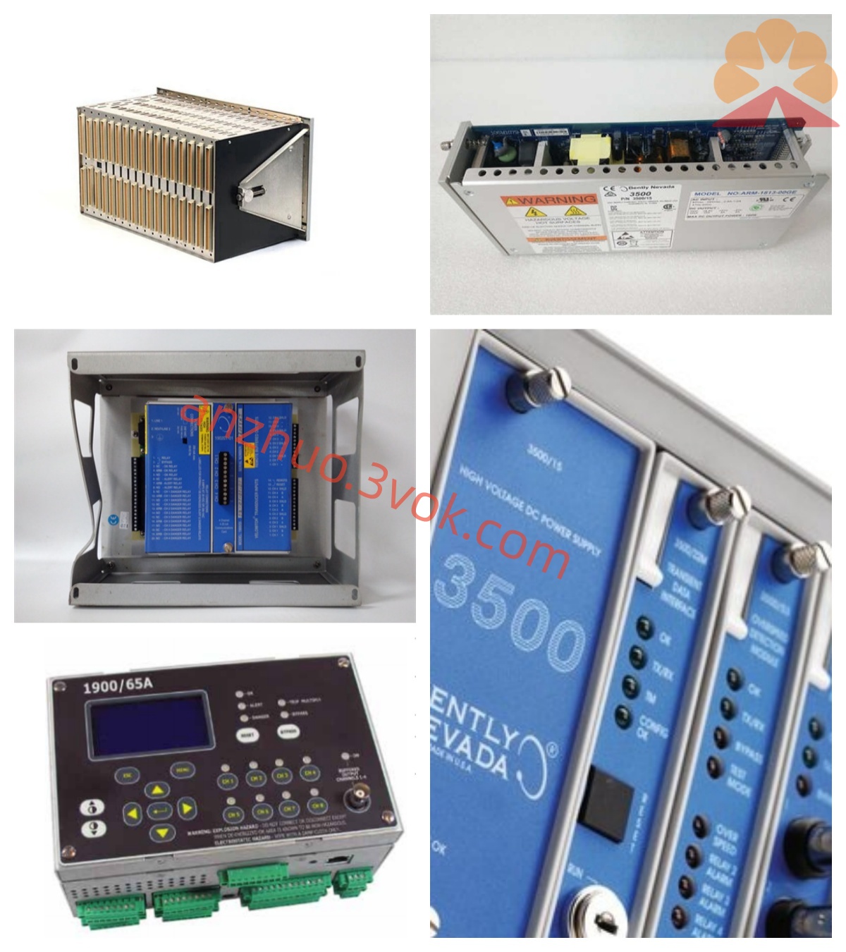
Bently Nevada 3300/46-XX-02-01-00 Interface I/O Module
Description
Bentley 3300/46-XX-02-01-00 Sloping Differential Expansion Monitoring Module Detailed Product Description
I. Product Overview
The Bentley 3300/46-XX-02-01-00 is a sloping differential expansion (Differential Expansion) monitoring module of the 3300 series TSI (Turbo Generator Monitoring Instrument) system developed by Baker Hughes (formerly GE Bentley Nevada), specifically designed for precise online monitoring of the relative thermal expansion (Differential Expansion) between the rotor and the casing of large steam turbines, gas turbines, and other rotating machinery. It adopts the measurement principle of the rotor's sloping surface combined with dual eddy current probes, expanding the sensor's linear range by several times to address the insufficient measurement range of traditional differential expansion monitoring, preventing severe accidents such as dynamic friction, axial collision wear, and unit tripping due to excessive thermal expansion differences between the rotor and the casing.
The module is a 19-inch standard rack-mounted, hot-swappable design, compatible with 3300 series vibration, shaft displacement, casing expansion, speed, etc. modules, sharing the backplane - 24V DC power supply and system bus. It is compatible with Bentley 3300 series eddy current probes (8mm/11mm/14mm/25mm/35mm), with dual probe input and single-channel differential expansion calculation, and includes dual-level alarm relays (ALERT + DANGER), conforming to API 670 standards, suitable for high-temperature, high-pressure, and strong electromagnetic interference environments. It is one of the core protection modules for turbine safety monitoring.
II. Model Coding Rules (3300/46-AA-DD-BB-CC)
3300: Bentley 3300 modular TSI system, unified rack, centralized power supply, hot-swappable, multi-module mixed installation architecture.
46: Function code, sloping differential expansion monitoring module, monitoring the relative thermal expansion between the rotor and the casing.
AA (Range / Measurement Range, XX corresponds to specific codes):
01 = 5 - 0 - 5mm; 02 = 0 - 10mm; 05 = 10 - 0 - 10mm; 06 = 0 - 20mm; 03 = 0.25 - 0 - 0.25in; 04 = 0 - 0.5in; 07 = 0.5 - 0 - 0.5in; 08 = 0 - 1.0in.
DD (Probe Specification / Sensitivity):
01 = 11mm, 100mV/mil; 02 = 14mm, 100mV/mil; 03 = 25mm, 20mV/mil; 04 = 35mm, sealed four-core.
BB (Relay Configuration, Fixed 02): 02 = Dual Relays (Warning ALERT + Danger DANGER).
CC (Certification Level, Fixed 01): 01 = General Industrial Safety Certification (Compliant with API 670, CE, UL).
00 at the end: No safety barrier (not applicable in non-explosion-proof areas).
III. Core Functions
1. Signal Acquisition and Sloping Differential Expansion Calculation
Using dual probes (A/B) + 8° sloping surface measurement principle of the rotor, the probe's 4mm linear range is expanded to approximately 28.7mm, meeting the typical differential expansion range of 0 - 20mm. The dual probe signals are superimposed for calculation, eliminating axial displacement and vibration interference, accurately outputting the differential expansion value (including positive and negative directions) relative to the casing of the rotor; the built-in signal conditioning circuit is compatible with the original 3300 series eddy current probes, with input signal -24V DC, input impedance 10kΩ, strong anti-common-mode interference ability.
2. High Precision Differential Expansion Measurement Range: Optional 5-0-5mm, 0-10mm, 10-0-10mm, 0-20mm, etc. (according to AA code).
Measurement accuracy: ≤ ±0.1% of full scale (25℃), resolution 0.01mm.
Frequency response: DC–10Hz, suitable for slow changes in thermal expansion.
Probe power supply: -24V DC (±10%), unified power supply on the back panel, supports short-circuit block switching for -18V DC to accommodate different probes.
3. Two-stage relay alarm output (ALERT + DANGER)
Configure two epoxy resin sealed SPDT relays for moisture-proof, dust-proof and anti-interference:
ALERT (warning): Triggered when the difference expansion value approaches the limit, reminding operation and maintenance to pay attention to the thermal expansion trend and adjust the load.
DANGER (danger): Triggered when the difference expansion value exceeds the limit or the signal is abnormal,the unit interlock protection and emergency shutdown.
Contact specifications: 250V AC/5A, 30V DC/5A, can directly drive sound and light alarms, DCS/PLC or interlock circuits.
Alarm threshold and delay: Independent settings for positive and negative direction thresholds, adjustable delay 0–10 seconds, filtering instantaneous fluctuations.
4. Front panel display and local configuration
Display: LCD digital window + status LED, real-time display of difference expansion value (including positive and negative), probe status; OK, ALERT, DANGER, BYPASS four groups of LED, intuitively display operation, alarm, bypass, fault status.
Configuration: Key-based local programming, no need for upper computer to set range, alarm threshold, delay, probe calibration parameters, slope angle compensation, positive and negative direction definition.
5. Isolated buffered signal output
The rear panel terminals provide a single isolated analog output (4–20mA or 0–10V optional), electrically isolated from the power supply, input signal ≥ 2500V AC, can send the difference expansion signal to the recorder, DCS, oscilloscope or external system for data recording, trend analysis and fault tracing.
6. Comprehensive self-diagnosis and fault identification
24-hour real-time monitoring: probe break / short circuit, signal over-limit, power abnormality, module hardware failure, probe calibration abnormality, slope surface wear; can distinguish real difference expansion anomalies from sensor / circuit faults, panel LED clearly indicates the fault type, facilitating rapid troubleshooting.
7. Strong anti-interference and system integration
Metal shielding shell, input/output/power electrical isolation ≥ 2500V AC, anti-common-mode interference, suitable for variable frequency equipment, high-voltage cabinets, etc. strong electromagnetic environment.
Compatible with 3300 series system bus (type A), can be connected to System 1 status monitoring software, realize remote configuration, data storage, trend analysis, fault recording and remote access.
4. Technical parameters
Measurement parameters
Monitoring channels: dual probe input, single-channel difference expansion calculation.
Compatible sensors: 3300 series eddy current probes (11/14/25/35mm, according to DD code).
Measurement range: 5-0-5mm, 0-10mm, 10-0-10mm, 0-20mm, etc. (according to AA code).
Measurement accuracy: ≤ ±0.1% of full scale (25℃), resolution 0.01mm.
Frequency response: DC–10Hz.
Input impedance: 10kΩ, input voltage -24V DC.
Measurement principle: 8° slope surface + dual probe superposition calculation.
Electrical parameters
Working power supply: -24V DC (±10%), back panel power supply; supports short-circuit switching -18V DC.
Power consumption: typical 3W, maximum ≤ 4W. Relay output: 2 SPDT channels, 250V AC/5A, 30V DC/5A.
Buffer output: 1 isolated analog signal (4–20mA/0–10V selectable).
Isolation strength: ≥2500V AC between input/output/power supply.
Environmental and mechanical parameters
Operating temperature: 0℃~+65℃ (standard type).
Storage temperature: –40℃~+85℃.
Relative humidity: 5%–95% (no condensation).
Installation method: 19-inch standard rack slot, supports hot swapping.
Dimensions: 203mm (height) × 330mm (depth) × 51mm (width).
Weight: Approximately 1.6kg.
Protection level: IP20 (installed in control cabinet).
Certification and compliance
Industry standards: Compliant with API 670 Rotating Machinery Monitoring and Protection Standards.
Electromagnetic compatibility: CE certification, compliant with EN 61000-6-2/4.
Safety and environmental protection: UL certification, RoHS compliance.
V. Structural Design
Module: Integrated compact frame structure, divided into front panel, internal circuit, and rear terminal block. The front panel integrates LCD digital display window, multiple groups of LED status indicator lights and local operation buttons. It can display differential expansion values, probe status and alarm information, complete parameter configuration, and operate intuitively and conveniently. The internal circuit includes dual probe signal conditioning unit, slope differential expansion calculation circuit, alarm comparison circuit, relay drive circuit and self-diagnosis unit. The functional zones are clear, the layout is compact, the metal shielding layer suppresses internal interference, ensuring long-term stable operation. The rear terminal block is clearly divided and marked, covering dual probe input, relay output, buffer output, power and communication interfaces. The wiring is convenient, facilitating on-site construction and maintenance. The module and the frame use gold-plated connectors, with reliable contact, wear-resistant and oxidation-resistant, stable electrical connection during hot swapping, no need to stop the machine for module replacement, reducing the impact of maintenance on production.
VI. System Compatibility
Hardware compatibility
Frame and power supply: Compatible with 3300 series 19-inch frame, power module, system monitoring module, can be installed with vibration, shaft displacement, shell expansion, speed and other modules.
Sensors: Fully compatible with original 3300 series eddy current probes (11/14/25/35mm), same specifications can be directly interchanged.
Output connection: Relay contacts connected to audible and visual alarms, DCS/PLC, interlock circuits; Buffer output connected to recorders, oscilloscopes, external instruments.
Software compatibility
Configuration software: Compatible with 3300 series dedicated configuration software, supports remote parameter configuration, alarm logic editing, firmware upgrade.
Monitoring software: Connected to System 1 platform, realizes real-time data, trend analysis, fault recording, report generation and remote access.
VII. Typical Application Scenarios
Power industry: Rotor–shell differential expansion monitoring of steam turbine rotors in thermal power plants/nuclear power plants, tracking thermal expansion differences during start-up, load increase processes, dual-level alarm linkage and interlock, preventing dynamic friction, axial rubbing, ensuring safe start-up and stable operation of the unit.
Petrochemical industry: Differential expansion monitoring of large-scale process turbines, centrifugal compressors rotors, tracking thermal deformation under high-temperature conditions, differential expansion over-limit alarm, preventing equipment deformation, misalignment failure leading to production interruptions.
Metallurgical industry: Differential expansion monitoring of high-temperature turbines, large transmission turbines rotors, tracking thermal expansion trends during start-up and load increase processes, warning and linkage alarms, reducing equipment failure shutdown risks.
VIII. Installation and Maintenance Specifications
Installation requirements
Frame installation: Push in smoothly into the vacant slot of the 3300 frame, ensure that the rear connectors are fully engaged, tighten the panel screws to prevent loosening. Probe wiring: Connect the dual probe cable according to the A/B channel markings, with the shielding layer grounded at one end and to suppress electromagnetic interference.
Alarm wiring: Distinguish between the ALERT and DANGER contacts, and connect them to the alarm/interlock circuit to confirm the logic is correct.
Power-up configuration: Confirm that the -24V DC power supply is normal, and set the range, alarm threshold, delay, probe calibration parameters, slope angle compensation, and save them through the panel or software.
Probe installation: Fix the dual probes symmetrically on both sides of the rotor slope surface, strictly control the installation gap (4mm linear zone) and coaxiality, secure them firmly, protect the cables well, and avoid vibration wear.
Daily maintenance
Inspection: Observe the panel display and LED status, confirm that the differential expansion value is normal and there are no fault alarms; check that the terminals are not loose, oxidized, or overheated.
Calibration: Calibrate the accuracy annually using a standard displacement generator, in accordance with API 670 standards; regularly check the probe linearity, slope surface wear condition.
Cleaning: Regularly clean the dust on the module and the rack to ensure ventilation and heat dissipation, and avoid dust-induced short circuits or poor heat dissipation.
Replacement of spare parts: When the module, probe, or cable is damaged, it must be replaced with the original Bentley model of the same type to ensure compatibility and measurement accuracy.
IX. Usage Precautions
This model is not explosion-proof. It is strictly prohibited to install and use it in flammable and explosive hazardous areas; for explosion-proof conditions, select the model with an intrinsic safety safety barrier.
It must be paired with the original Bentley 3300 series eddy current probe (matching DD code specifications). Different specifications of probes cannot be mixed; otherwise, the signals will not match and the measurement will fail.
The installation gap and coaxiality of the probe must be set strictly according to the manual. Installation deviations will cause signal distortion and increase measurement errors; the slope surface must be checked regularly for wear.
It is strictly prohibited to disassemble the module, modify the internal circuitry, or modify the probe calibration parameters without authorization. Illegal operations will cause equipment damage and invalid warranty.
Before wiring, maintenance, or replacing the module, cut off the power supply of the rack to prevent short circuits and electric shock accidents.
Alarm threshold and delay must be set in combination with the unit's process parameters. Improper parameters will lead to frequent false alarms or warning failures.
The installation location should be far away from frequency converters, transformers, high-voltage cabinets, etc., which are strong electromagnetic interference sources, to reduce signal interference and ensure stable monitoring.
Get a Quote