
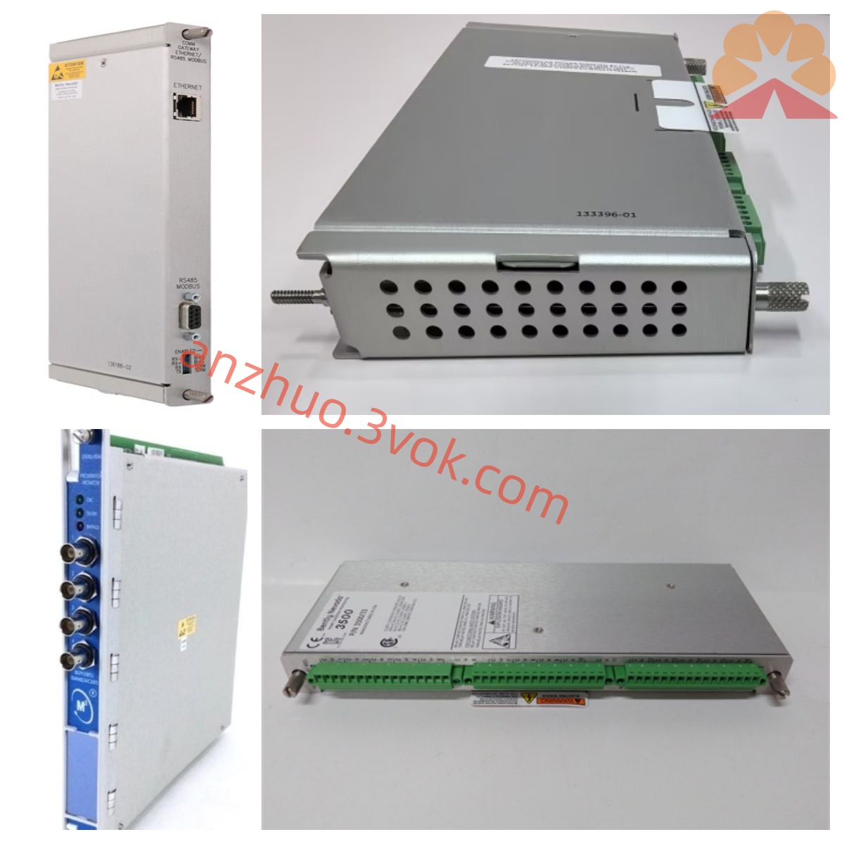
Bently Nevada 3300/50-02-01-00-00 Vibration Monitoring Module
Description
Bentley 3300/50-02-01-00-00 Speed Monitoring Module Detailed Product Description
I. Product Overview
The Bentley 3300/50-02-01-00-00 belongs to the Beckhusey's Bentley Nevada 3300 series TSI turbine monitoring instrument system. It is a dedicated single-channel speed monitoring module, mainly used for continuous online monitoring of the shaft speed and zero speed of various rotating machinery. This module is compatible with electro-vortex probes and magnetic-electric speed sensors, and can capture the speed changes of the unit under normal operation, start-stop, and turning gear conditions in real time. It issues warning signals for overspeed, underspeed, and abnormal shutdown states, and is widely used in turbine, gas turbine, centrifugal compressor, large fans, pumps, and drive motors and other key equipment in the power, petrochemical, metallurgy, water treatment and other fields. The product adopts a common 19-inch rack structure design for the industry, supports hot-swapping, and can complete module disassembly, replacement, and module installation under the condition of the continuous power supply of the entire TSI system, providing reliable speed monitoring guarantee for the stable operation of the unit.
II. Model Coding Rules
The complete model coding format of this product is 3300/50-XX-XX-XX-XX. The definitions of each section code are as follows. 3300 represents the Bentley 3300 series modular TSI system, which adopts centralized power supply, multi-module mixed installation architecture, standard 19-inch rack installation and supports hot swapping. 50 is the function code, representing the single-channel speed monitoring module, and the core function is to collect, process and output alarm signals for speed and zero speed signals. The first code 02 represents the basic speed monitoring type, with the module's core function being shaft speed measurement, and it also includes zero speed detection. It does not focus on rotor acceleration monitoring. The second code 01 represents the relay configuration type, equipped with epoxy resin sealed single-channel warning relay, with moisture-proof, dust-proof, and anti-environmental interference capabilities. The third code 00 represents no third-party special certification, as a standard configuration. The fourth code 00 represents that the module does not integrate a safety barrier, belonging to a non-explosion-proof structure, and is only applicable to conventional non-hazardous operation areas.
III. Core Functions
This module adopts a dual-channel sensor input design and is equipped with hardware signal voting logic. It can simultaneously connect two speed sensor signals. When one of the sensors has a broken wire, short circuit or abnormal signal, the system will automatically switch to the normal signal circuit, effectively avoiding monitoring interruption or false alarms caused by a single sensor failure, significantly improving the stability of equipment operation monitoring. The module focuses on precise speed measurement. The speed range can be set on-site, and it integrates a zero speed judgment function, capable of accurately identifying the unit's shutdown, turning gear status, providing reliable signal basis for unit start-stop interlock, turning gear device linkage, etc.
The device is equipped with a high-precision signal processing circuit, with fast measurement response speed and small numerical deviation. The panel is equipped with status indicator lights and display units, which can intuitively display real-time speed, module operation status, alarm status and bypass status. It is compatible with simple operation buttons and supports on-site parameter setting without relying on an upper-level device to complete basic configuration. The module is equipped with a single-channel passive warning relay output. The relay contacts are sealed and work stably and reliably. The speed alarm threshold and alarm delay can be flexibly programmed, capable of filtering instantaneous speed fluctuations to avoid false triggering, and the output signal can be directly connected to audible and visual alarm devices, DCS or PLC control systems.
The module also includes a buffered isolation signal output port, which can synchronously transmit the collected speed raw signals to external devices such as recorders, oscilloscopes for data recording and in-depth analysis. The entire machine is equipped with a complete self-diagnosis function. It can monitor sensor circuit faults, signal over-limitations, module power supply abnormalities, and hardware failures at all times. It can clearly distinguish between the actual abnormal speed of the equipment and line or component failures, facilitating the rapid troubleshooting by maintenance personnel. The machine adopts a metal shielding structure, with electrical isolation between the internal circuits and the input, output, and power circuits. It has strong anti-electromagnetic interference capability and can adapt to complex electromagnetic environments such as on-site frequency converters and high-voltage distribution cabinets. At the same time, it is compatible with the 3300 series system bus and can be connected to the System 1 equipment status monitoring software to achieve remote parameter configuration, historical data storage, operation trend analysis, and fault tracing.
Five. Technical Parameters
Measurement Parameters
The monitoring form is single-channel monitoring, with dual-channel sensor redundant input. The compatible sensors are the original Bently eddy current speed probes and magnetic-electric speed sensors. The speed measurement range can be programmed and set, with a maximum coverage of 0 to 50000 revolutions per minute. The zero-speed identification threshold can be set within the range of 0 to 5 revolutions per minute. The overall measurement accuracy does not exceed 0.1% of the full scale, and the speed display resolution can reach 0.1 revolutions per minute. The module is equipped with a single-level speed warning function. The alarm threshold and alarm delay can be adjusted, with the delay adjustment range being 0 to 10 seconds.
Electrical Parameters
The working power supply uses -24 volt DC power supply, with a voltage allowable fluctuation range of 10% of the nominal value. It is uniformly powered by the 3300 series rack backplane. The overall power consumption of the module does not exceed 3 watts, and the operating current is stable. The sensor input is in the form of pulse signals, and the input impedance is fully matched with the standard parameters of the accompanying speed sensor. The relay output is a single-sealed SPDT passive contact point, with a rated load of 250 volts AC/3 amperes DC/3 amperes AC. The external buffer output is an isolated signal, which can be connected to various secondary monitoring devices. The electrical isolation strength between the module input, output, and power is no less than 2500 volts AC, and the anti-common-mode interference ability is excellent.
Environmental and Mechanical Parameters
The standard working temperature range is from -30 degrees Celsius to 65 degrees Celsius, and the storage temperature range is from -40 degrees Celsius to 85 degrees Celsius. The working environmental relative humidity range is 0% to 95%, and it requires no condensation. The installation method is 19-inch standard rack slot installation, supporting online hot plugging. The overall machine size is 254 millimeters by 165 millimeters by 63.5 millimeters, and the weight is approximately 1.2 kilograms. The panel and shell have characteristics of shock resistance, corrosion resistance, and oil resistance. The equipment protection level is IP20, suitable for installation in indoor control cabinets.
Certification and Compliance
The product design and performance comply with the API 670 rotating machinery monitoring protection industry standards. In terms of electromagnetic compatibility, it has CE certification, following the EN 61000-6-2 and EN 61000-6-4 relevant specifications. At the same time, it meets UL safety standards and RoHS environmental protection requirements. The module has no explosion-proof structure and built-in safety barrier, and is prohibited from use in flammable and explosive, or areas with combustible gases or dust.
Five. Structural Design
The module is overall designed with an integrated compact rack structure, mainly divided into the front panel, internal main control circuit, and rear wiring terminals. The front panel integrates the speed display unit, multiple groups of LED status indicators, and local operation keys. Maintenance personnel can directly view the real-time speed, module operation status, alarm status, and bypass status on the panel, and complete parameter settings such as range, threshold, and delay. The operation is convenient and intuitive. The internal circuitry includes two independent signal conditioning units, a signal voting logic circuit, a speed calculation processing unit, an alarm comparison circuit, and a relay drive circuit. Each functional area is clearly divided and the circuit layout is reasonable, effectively avoiding signal interference and ensuring long-term stable operation.
The rear wiring terminals are clearly zoned, with two sensor input terminals, an alarm relay output terminal, a buffer signal output terminal, as well as system power and communication interfaces. The terminal markings are clear and regular, facilitating on-site wiring, line inspection, and daily maintenance. The connection part between the module and the frame uses gold-plated connectors, with excellent contact performance, wear resistance, and oxidation resistance, fully ensuring the reliability of electrical connection during hot swapping. When replacing the module, the entire TSI system does not need to be stopped, minimizing the impact of equipment maintenance on the production and operation of the unit.
Six. System Compatibility
Hardware Compatibility
At the hardware level, it can fully match all standard 19-inch frames, system power modules, and system monitoring modules of the 3300 series, and can be installed and work collaboratively with various functional modules such as vibration monitoring, shaft displacement monitoring, and temperature monitoring of the same series. The sensor end can directly be used with the original Bently electromagnetic flow velocity probe and magnetic-electric speed sensors, and sensors of the same specification can be directly interchanged without re-calibrating parameters. The output port adaptability is extensive. The relay dry contacts can be connected to sound and light alarms, unit interlock circuits, DCS and PLC analog input terminals, and isolated buffer signals can be connected to paper recorders, oscilloscopes, external monitoring instruments, etc.
Software Compatibility
Software compatibility is with the 3300 series dedicated configuration software, supporting remote online parameter configuration, alarm logic editing, and module firmware upgrade. At the same time, it can be connected to the System 1 equipment status monitoring management software to achieve real-time speed data collection, trend drawing, fault record storage, data report generation, and remote access management, helping to manage the equipment's full life cycle status.
Seven. Typical Application Scenarios
In the power industry, this module is mainly applied to steam turbines, generators, induced draft fans, and supply fans of thermal power plants, monitoring the normal operating speed of the unit, speed changes during start-up and shutdown, and zero-speed state after shutdown, providing signal support for the联动 of the cranking device and abnormal speed warning. In the petrochemical industry, it is mostly used in centrifugal compressors, process turbines, and large process pumps in non-explosion-proof areas, monitoring speed conditions in real time, preventing production failures caused by excessive speed or insufficient speed, and ensuring the continuous and stable operation of the chemical plant.
In the metallurgical industry, it is adapted to high-temperature fan main units, sintering system fans, large transmission motors, etc., monitoring the speed status of equipment throughout the process, promptly detecting potential speed fluctuation hazards, and reducing the probability of equipment failure and downtime. In the cement, papermaking, water treatment, and other general industrial fields, it can be used for online speed monitoring and status warning of rotating machinery such as large coal mills, various fans, and high-power water pumps, combined with the control system to achieve basic interlock protection, extending equipment service life, and reducing maintenance costs.
Eight. Installation and Maintenance Specifications
Installation Requirements
When installing the frame, push the module smoothly into the vacant slot of the 3300 frame, ensure that the rear connectors are fully engaged, and then tighten the panel fixing screws to prevent the module from loosening during operation. The wiring of the sensors must be connected according to the channel markings to the sensor signal cables, and all signal cable shielding layers use single-ended grounding to suppress on-site electromagnetic interference. The alarm circuit wiring is constructed according to the design drawings, accurately distinguishing the types of relay contacts to ensure correct alarm and interlock logic.
After completing the wiring, confirm that the 24-volt DC power supply of the frame is normal. Through the panel buttons or the upper-level configuration software, set and save parameters such as speed range, zero-speed threshold, alarm value, and delay. The speed sensor is installed at the end of the equipment shaft or at the corresponding position of the speed measuring gear disc. The installation gap must be strictly controlled in accordance with the sensor technical requirements. The probe should be firmly fixed, and the matching cable should be well protected and fixed to avoid cable wear and displacement caused by equipment vibration.
Daily Maintenance
During the daily inspection process, regularly observe the display values on the panel and the status of the indicator lights to confirm that the speed monitoring data is normal, without faults or alarm prompts. At the same time, check all connection terminals to see if there are any loose, oxidized, or overheated phenomena. Any potential hazards should be dealt with promptly. According to the equipment operation cycle, use the standard speed generating device once a year to calibrate the module's measurement accuracy to ensure the measurement results comply with the API 670 standard requirements. Regularly clean the dust on the module surface and the slots in the rack to ensure good ventilation and heat dissipation conditions for the equipment, and avoid short circuits or poor heat dissipation caused by dust accumulation. When the module, sensor, or signal cable is damaged and needs to be replaced, only original Beltrini compatible parts of the same model should be selected. Non-compatible parts are prohibited to prevent signal abnormalities and measurement inaccuracies.
IX. Usage Precautions
This module is not designed for explosion-proof purposes. There is no safety barrier inside, and it is strictly prohibited to install and use it in flammable and explosive hazardous areas. The module is designed as a speed monitoring and warning device and cannot be used alone as the main overspeed protection device for the unit. The key unit's overspeed protection requires a dedicated triple redundant overspeed protection system. It must be used in combination with the original Beltrini compatible speed sensor. Different specifications of sensors cannot be mixed, otherwise, signal mismatch and measurement failure will occur.
The installation gap of the speed sensor must strictly follow the product technical requirements. An excessive or insufficient gap will cause signal distortion and increased measurement error. It is strictly prohibited to disassemble the module shell, modify the internal circuitry, or modify the factory-calibrated parameters of the sensor. Irregular operations will directly cause equipment damage and loss of product warranty services. Before conducting line maintenance, module replacement, and other operations, it is necessary to cut off the power supply of the rack to prevent short circuits and electric shock accidents.
The speed alarm threshold, delay, etc. need to be set according to the actual operation process of the unit. Unreasonable parameter settings will cause protection failure or frequent false alarms. The installation position of the module should be as far away as possible from power frequency converters, transformers, high-voltage switch cabinets, etc., which are strong electromagnetic interference sources. Reduce the interference of external electromagnetic signals on the speed pulse signal to ensure stable and accurate monitoring data.
Get a Quote