
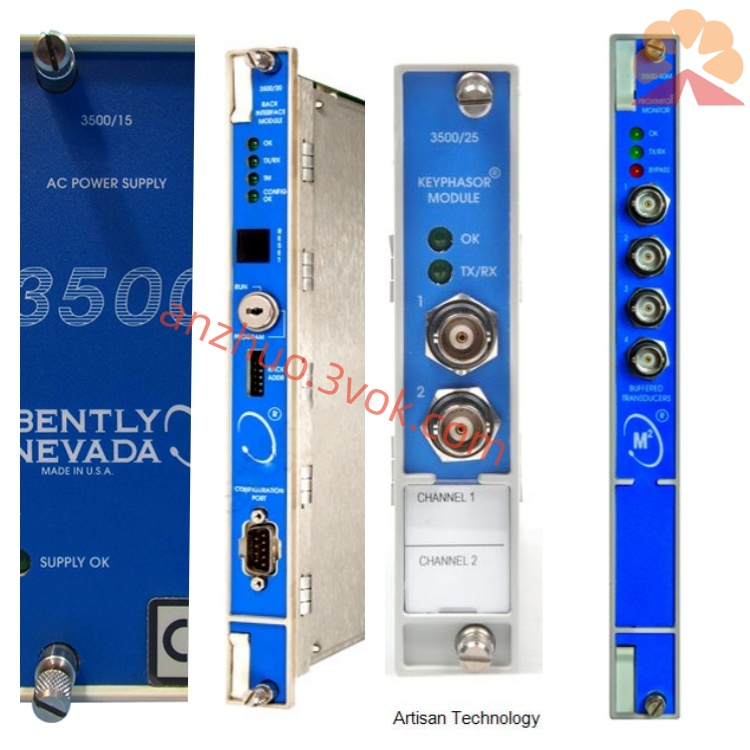
Bently Nevada 3300/50-03-01-00-00 Vibration Monitoring Module
Description
Bentley 3300/50-03-01-00-00 Speed/Acceleration Monitoring Module Detailed Product Description
I. Product Overview
The Bentley 3300/50-03-01-00-00 is a rotor acceleration speed monitoring module of the TSI (Turbo Generator Instrumentation) series of the Nevada 3300 model under Baker Hughes (formerly GE). It belongs to a single-channel precision speed monitoring unit, specifically designed for continuous online monitoring of the rotational speed, rotor acceleration, and zero speed of rotating machinery. It receives signals from two eddy current probes or magnetic-electric speed sensors, and has built-in voting logic. In the event of a single sensor failure, it can avoid false alarms and monitoring interruptions, and is suitable for key equipment in industries such as power, petrochemical, and metallurgy, including steam turbines, compressors, fans, pumps, motors, etc., for monitoring overspeed, underspeed, zero speed, and abnormal rotor acceleration, providing early warnings and status feedback. It cannot be used independently as an overspeed protection system. The module is installed in a 19-inch standard rack and supports hot swapping, and is compatible with the 3300 series rack and power supply system.
II. Model Coding Rules (3300/50-XX-XX-XX-XX)
3300: Bentley 3300 modular TSI system, 19-inch rack, centralized power supply, supports hot swapping and mixed installation of multiple modules.
50: Function code, speed/acceleration monitoring module (Tachometer), for monitoring the rotational speed, rotor acceleration, and zero speed of the shaft.
The 1st position (Monitoring Type): 03 = Rotor Acceleration Speed Meter, prioritizes rotor acceleration monitoring, and also supports speed measurement.
The 2nd position (Relay Type): 01 = Epoxy Resin Sealed Warning Relay, single warning relay output, moisture-proof and dust-proof.
The 3rd position (Certification Option): 00 = No Intrinsic Safety Certification, standard type without additional explosion-proof or safety certification.
The 4th position (Safety Barrier Option): 00 = No Safety Barrier, non-explosion-proof design, suitable for non-hazardous areas.
III. Core Functions
Dual Sensor Input and Voting Logic
Single-channel monitoring unit, capable of connecting two speed sensors (eddy current probes, magnetic-electric speed sensors), with built-in hardware voting logic. When one sensor is disconnected, short-circuited, or has an abnormal signal, it automatically switches to the normal signal to avoid false alarms or monitoring interruptions caused by a single sensor failure, enhancing reliability.
Dual Parameter Monitoring of Speed and Rotor Acceleration
Accurate measurement of real-time rotational speed (RPM) and rotor acceleration (RPM/s) of the rotating shaft. The speed range is 0–50000 RPM, with a sensitive acceleration response, capable of early identification of speed changes, rotor acceleration abnormalities, etc., suitable for monitoring during unit start-up, acceleration, and deceleration processes.
Zero Speed Detection
Has an independent zero speed judgment function, allowing the setting of a zero speed threshold (e.g., ≤1 RPM), used for confirming the unit shutdown state,联动 control of the turning gear, to prevent incorrect startup or equipment reversal.
High Precision Signal Processing and Display
Measurement accuracy ≤ ±0.1% of full scale, resolution 0.1 RPM, response time fast. The front panel integrates an analog display head and digital display, real-time displays the speed value; equipped with OK, ALERT, DANGER, BYPASS LED indicators, intuitive viewing of module status, alarms, and bypass status.
Programmable Warning Relay Output
Equipped with 1 epoxy resin sealed SPDT warning relay (ALERT), rated load 250V AC/3A, 30V DC/3A, can independently set speed or acceleration warning thresholds, alarm delay 0–10 seconds programmable, filtering transient fluctuations, output to audible and visual alarms or DCS/PLC.
Buffered Signal Output The rear terminals provide two isolated buffer outputs, which can synchronously send the rotational speed/acceleration signals to the recorder, oscilloscope or external monitoring system for data recording and secondary analysis.
Comprehensive self-diagnosis and fault identification
24-hour monitoring of sensor faults, signal over-limit, power supply abnormalities, module hardware faults, distinguishing mechanical rotational speed abnormalities from sensor/loop faults. The panel LEDs synchronously display the fault types, reducing the difficulty of maintenance and troubleshooting.
Strong anti-interference and system integration
Metal shielding enclosure, electrical isolation between input/output/power supply, common-mode interference resistance ≥ 2500V AC, suitable for frequency converters, high-voltage equipment and other strong electromagnetic environments. Compatible with 3300 system bus, can be connected to System 1 status monitoring software to achieve remote configuration, data storage, trend analysis.
Technical parameters
Measurement parameters
Monitoring channel: single channel (voting of dual sensor inputs).
Sensor compatibility: eddy current rotational speed probe, magnetic-electric speed sensor (original Bently).
Rotational speed range: 0–50000 RPM (programmable range).
Acceleration measurement: rotor acceleration (RPM/s), response time ≤ 100ms.
Zero rotational speed threshold: 0–5 RPM programmable.
Measurement accuracy: ≤ ±0.1% full scale, resolution 0.1 RPM.
Alarm settings: single-level warning (ALERT), independent setting of rotational speed/acceleration thresholds, delay 0–10s adjustable.
Electrical parameters
Power supply: -24V DC (±10%), backplane power supply of the machine.
Power consumption: ≤ 3W, typical 1.5W.
Sensor input: two pulse signals, input impedance matched to Bently rotational speed sensor.
Relay output: 1 SPDT passive contact (epoxy resin sealed), 250V AC/3A, 30V DC/3A.
Buffer output: two isolated analog signals (rotational speed/acceleration), compatible with external equipment connection.
Isolation performance: isolation between input/output/power supply ≥ 2500V AC.
Environmental and mechanical
Operating temperature: -30℃ ~ +65℃ (standard type).
Storage temperature: -40℃ ~ +85℃.
Relative humidity: 0%–95% (no condensation).
Installation: 19-inch standard rack slot, hot-swappable.
Size: 254mm × 165mm × 63.5mm.
Weight: approximately 1.2kg.
Protection level: IP20 (in the control cabinet).
Certification and compliance
Industry standards: comply with API 670 (version 4/5) rotating machinery monitoring standards.
Electromagnetic compatibility: CE certification, compliant with EN 61000-6-2/4.
Safety: UL, RoHS compliance.
Explosion-proof: non-explosion-proof design, no safety barrier, only applicable to non-flammable and non-explosive areas.
Five. Structural design
The module adopts a standard rack structure, compact layout, divided into front panel, main circuit, and rear terminals. The front panel integrates analog display head, digital display window and LED status indicator light, combined with simple operation keys, can locally view the real-time value of rotational speed/acceleration, alarm status, complete threshold and delay configuration. The internal circuit contains dual sensor signal conditioning unit, voting logic circuit, rotational speed/acceleration calculation unit, alarm comparison circuit and relay drive circuit, independent structure, strong anti-interference ability. The rear terminals are clearly zoned, containing two sensor input terminals, warning relay output terminals, buffer signal output terminals and power/communication interface, clearly marked, convenient for wiring and maintenance. Gold-plated connectors ensure reliable hot-swapping, replacing the module does not require shutdown.
Six. System compatibility
Hardware compatibility Rack and Power Supply: Compatible with 3300 series 19-inch racks, power modules, and system monitoring modules. Can be installed together with vibration, displacement, temperature and other modules.
Sensors: Fully compatible with Bently eddy current speed probes and magneto-electric speed sensors. The same specifications can be directly interchanged.
Output Connection: Relay contacts can be connected to audible and visual alarms, DCS/PLC dry contacts; Buffered output can be connected to recorders, oscilloscopes.
Software Compatibility
Configuration Software: Special configuration software for 3300 series, supporting remote parameter configuration, alarm logic editing, firmware upgrade.
Monitoring Software: System 1 equipment status monitoring software, realizing real-time data, trend, fault records, reports and remote access.
VII. Typical Application Scenarios
Power Industry: Monitoring of shaft speed and rotor acceleration for thermal power / gas turbine generators, abnormal speed increase / decrease during start-up/shutdown warning, zero-speed confirmation for turning gear status.
Petrochemical Industry: Monitoring of rotational speed for centrifugal compressors, process turbines, high-speed pump sets, overspeed / underspeed warning, rotor acceleration sudden change identification, protecting the unit from unstable operation.
Metallurgical Industry: Monitoring of rotational speed for blast furnace fans, sintering main exhaust fans, high-speed drive motors, monitoring of start-up/shutdown process status, preventing abnormal speed from causing equipment failure.
General Industry: Online monitoring of rotational speed for high-speed large rotating machinery (grinding mills, fans, pump sets) in cement, papermaking, water treatment industries, zero-speed interlock protection, abnormal acceleration warning.
VIII. Installation and Maintenance Specifications
Installation Requirements
Rack Installation: Insert the rack smoothly into the 3300 rack slot, ensure that the connectors are fully engaged, and tighten the panel screws.
Sensor Wiring: Connect two speed sensor cables according to channel numbers, single-ended grounding the shield layer to reduce interference.
Alarm Wiring: Connect the warning relay contacts to the alarm circuit, distinguish OK and ALERT contacts to ensure correct logic.
Power On Configuration: Confirm the normal -24V DC, then set the speed/acceleration thresholds, zero-speed value, alarm delay through the panel or software.
Sensor Installation: Fix the probe vertically/vertically at the shaft end or the radial position of the gear disk, with the gap meeting the sensor requirements, and fix it firmly.
Daily Maintenance
Inspection: Observe the panel display and LEDs, confirm that the speed data is normal and there are no fault alarms; check that the terminals are not loose, oxidized, or overheated.
Calibration: Calibrate the accuracy annually using a standard speed generator, in accordance with API 670 requirements.
Cleaning: Regularly clean the modules and racks of accumulated dust to ensure ventilation and heat dissipation.
Spares: Replace modules, sensors or cables must use Bently original parts to avoid compatibility issues.
IX. Usage Precautions
This module is non-explosion-proof. Do not use in flammable and explosive hazardous areas.
It cannot be used independently as an overspeed protection system. It is only used for status monitoring and warning; overspeed protection requires a dedicated triple-redundant overspeed protection device.
It must be paired with Bently original speed sensors; do not mix with other specifications, otherwise the signals will not match and the measurement will fail.
The sensor installation gap must be strictly set according to the manual; abnormal gaps will cause signal distortion and measurement error increase.
Do not disassemble the module, modify the circuit or modify the sensor calibration parameters privately; otherwise, the equipment will be damaged and the warranty will be invalid.
Before wiring, maintenance, or replacing the module, cut off the power supply of the rack to prevent short circuits and electric shock.
Alarm thresholds and delays must be set strictly according to the unit process, improper parameters will cause frequent false alarms or warning failures.
Install the module away from power frequency converters, transformers, high-voltage cabinets and other strong electromagnetic interference sources to reduce signal interference.
Get a Quote