
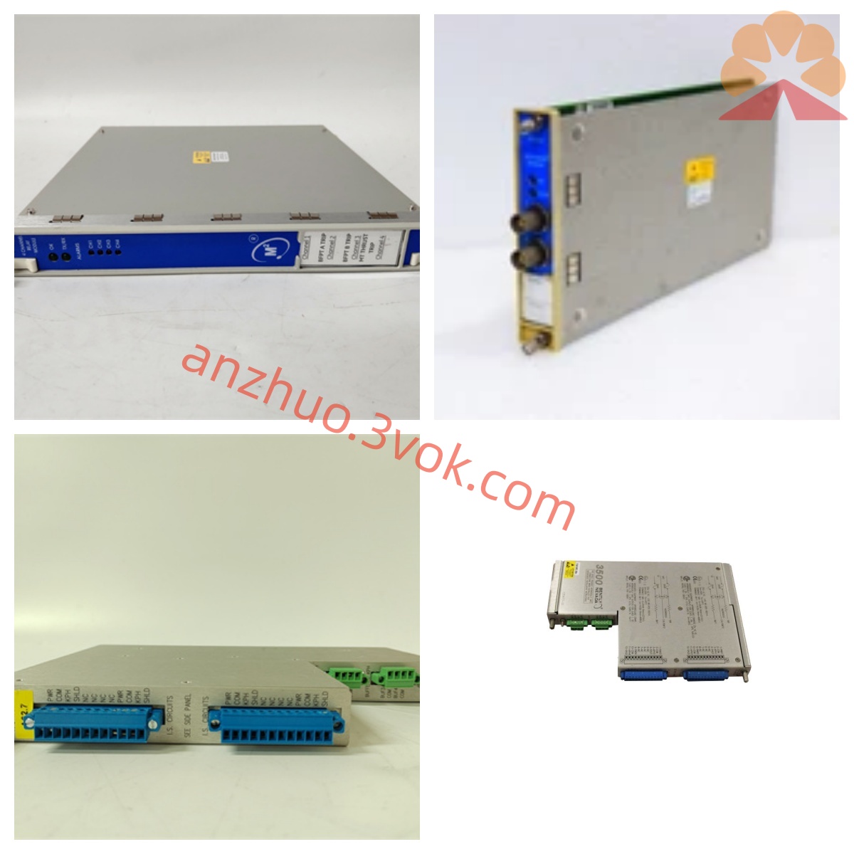
Bently Nevada 3300/55-01-04-02-02-00-00-04-00 Thrust Position Monitoring Module
Description
Bentley 3300/55-01-04-02-02-00-00-04-00 Dual-channel Speed Vibration Monitoring Module Detailed Product Description
I. Product Overview
The Bentley 3300/55-01-04-02-02-00-00-04-00 is a dual-channel speed vibration monitoring module within the 3300 series TSI (Turbo Generator Instrumentation) of Baker Hughes (formerly GE), used for high-precision online monitoring of absolute vibration speed of rotating / reciprocating mechanical bearing housings / shells. It is compatible with the Velomitor series seismic speed sensors and can capture mid-high frequency fault characteristics such as bearing wear, gear meshing, and structural resonance. It is widely used in non-explosive areas of power, petrochemical, and metallurgical industries for vibration protection and fault warning of equipment such as turbines, compressors, fans, pumps, and motors. The module adopts a standard 19-inch rack design, supports hot swapping, and can be replaced without power interruption, compatible with the 3300 series racks and power supply system.
II. Model Coding Rules (3300/55-XX-XX-XX-XX-XX-XX-XX-XX-XX)
3300: Bentley 3300 modular TSI system, standard 19-inch rack installation, supports multi-module combination, centralized power supply, and hot swapping.
55: Function code, defined as a dual-channel speed vibration monitoring module, processing two seismic speed sensor signals, measuring absolute vibration speed.
The 1st position (sensor sensitivity): 01 = 500 mV/in/s (high sensitivity Velomitor).
The 2nd position (frequency response): 04 = 10Hz~1000Hz (-3dB), covering mid-high frequency vibrations.
The 3rd position (range / channel 1): 02 = 0~2.0 mm/s pk (speed peak).
The 4th position (range / channel 2): 02 = 0~2.0 mm/s pk (speed peak).
The 5th position (Keyphasor interface): 00 = no speed synchronization input.
The 6th position (analog output): 00 = no 4-20mA/0-10V output.
The 7th position (relay configuration): 04 = 2 SPDT relays per channel (warning / danger), no common OK relay.
The 8th position (communication interface): 00 = no additional communication, compatible with 3300 system bus.
The 9th position (special function): 00 = standard type, no custom function. Support for speed / acceleration / displacement signal conversion (integration / differentiation), adaptable to different fault analysis requirements.
All-round fault self-diagnosis
Built-in OK self-check circuit, 24-hour monitoring for sensor disconnection, short circuit, signal over-limit, sensitivity abnormality, etc. of faults, accurately distinguishing mechanical faults from sensor circuit faults, reducing the probability of false alarms / false interlocks; panel LED synchronously displays OK, fault, bypass status of channels.
Programmable multi-level alarm and interlock
Each channel independently sets two levels of speed thresholds (Alert / Danger), alarm delay 0~10 seconds programmable, filtering instantaneous fluctuations; the entire machine is equipped with 4 SPDT non-polar relay contacts (2 contacts per channel), rated load 250V AC/3A, 30V DC/3A, directly connected to sound and light alarm and unit safety interlock circuits.
Local status display and operation
The front panel integrates a high-contrast light column display, synchronously displaying real-time values of dual-channel vibration speed and alarm status; combined with operation keys, local parameters settings such as range, filtering, alarm threshold, delay can be completed without an upper computer, operation is intuitive and convenient.
Strong anti-interference and system integration
Metal shielding structure, input / output / power circuit electrical isolation, anti-common-mode interference ≥ 2500V AC, resisting interference from frequency converters, high-voltage equipment; supports 3300 internal bus communication, compatible with System 1 monitoring software, enabling remote configuration, data storage, trend analysis and fault traceability.
Four. Technical parameters
Measurement parameters
Channel quantity: 2 completely independent synchronous isolated channels.
Sensor compatibility: Bently high-sensitivity Velomitor speed sensor (500 mV/in/s), high-temperature Velomitor system (HTVS).
Measurement range: 0~2.0 mm/s pk (speed peak, consistent for both channels).
Frequency response: 10Hz~1000Hz (-3dB), programmable filtering.
Sampling rate: 256 samples/second per channel.
Measurement accuracy: ≤±1% reading, resolution 0.1 mm/s, dynamic range > 80dB.
Signal conversion: Support speed ↔ acceleration ↔ displacement (integration / differentiation).
Alarm settings: Each channel two-level alarm (alert / danger), delay 0~10 seconds programmable.
Electrical parameters
Working power supply: -24V DC (allowable fluctuation ±10%), 3300 rack backplane power supply.
Power consumption: ≤3W, maximum working current 15mA.
Input impedance: Matching high-sensitivity Velomitor sensor standard input impedance.
Relay output: 4 SPDT non-polar contact points, 250V AC/3A, 30V DC/3A.
Isolation performance: Electrical isolation between input / output / power, anti-common-mode interference ≥ 2500V AC.
Environmental and mechanical parameters
Working temperature: -30℃~+65℃ (standard type).
Storage temperature: -40℃~+85℃.
Relative humidity: 0%~95% (no condensation).
Installation method: 3300 series standard 19-inch rack slot installation, supports hot swapping.
Shell material: Metal panel + flame-retardant engineering plastic, shock-resistant, corrosion-resistant, oil-resistant.
Protection level: IP20 (internal installation in control cabinet).
Size: 254mm×165mm×63.5mm (standard 3300 module size).
Weight: Approximately 1.2kg.
Certification and compliance Industry standard: Compliant with API 670 rotating machinery monitoring and protection standards.
Electromagnetic compatibility: CE certification, compliant with EN 61000-6-2 and EN 61000-6-4 standards.
Safety certification: UL and RoHS compliance.
Explosion-proof rating: Non-explosion-proof design, without built-in safety barrier, only applicable to non-flammable and non-explosive areas.
V. Structural Design
The module adopts a standard rack-based modular structure as a whole, with a compact layout, divided into three parts: front panel, internal main circuit, and rear terminal block. It is convenient for installation, wiring, and maintenance.
Front panel: Integrated with dual-channel light column display (real-time display of vibration velocity value), power / OK / alarm / fault LED indicators, and operation keys. It enables on-site data viewing, alarm status checking, parameter configuration, and intuitive operation.
Internal main circuit: Two completely independent signal processing units (corresponding to channels 1/2), each containing signal conditioning, filtering, high-speed sampling, calculation, alarm comparison, and relay drive circuits. There is no electrical connection between channels, and a single-point failure does not affect the other channel.
Back terminal block: Partitioned layout, clearly dividing dual-channel sensor input terminals, 4-channel relay alarm terminals, power terminals, and system communication interfaces. The markings are clear, the wiring is neat, and it is convenient for wiring, inspection, and maintenance.
Hot-swappable design: The module and the backplane of the rack use gold-plated connectors for reliable connection, supporting online insertion and removal. Replacing the module does not require shutting down the entire TSI system, reducing the impact of maintenance on the operation of the unit.
VI. System Compatibility
Hardware Compatibility
Rack and power supply: Perfectly compatible with 3300 series standard 19-inch racks, system power modules, and system monitoring modules. Modules with the same series of vibration, displacement, and speed functions can be installed and work together.
Sensing components: Fully compatible with Bently high-sensitivity Velomitor (500 mV/in/s) and high-temperature Velomitor (HTVS) speed sensors. Sensors of the same specification can be directly interchanged without recalibration.
Output connection: Relay contacts can be connected to sound and light alarms, unit interlock circuits, DCS/PLC dry contact inputs to achieve alarm and protection linkage.
Software Compatibility
Configuration software: Compatible with 3300 series dedicated configuration software, supporting remote parameter configuration, alarm logic editing, filtering settings, and firmware upgrades.
Monitoring software: Compatible with System 1 equipment status monitoring software, enabling real-time vibration data collection, trend analysis, fault record storage, report generation, and remote access, supporting the full life cycle management of equipment.
VII. Typical Application Scenarios
Power industry: High-speed turbine and gas turbine bearing housings/shells in thermal power plants for absolute vibration monitoring, accurately warning of bearing wear, gear meshing faults, structural resonance, etc., ensuring the safe and stable operation of the main unit.
Petrochemical industry: Vibration monitoring of centrifugal compressors, process turbines, and high-speed pump groups in non-explosion-proof areas, avoiding unplanned shutdowns caused by medium-frequency faults, ensuring continuous production.
Metallurgical industry: Bearing housings of blast furnaces, sintering main exhaust fans, high-speed drive motors for vibration monitoring, predicting bearing failure, gear faults, resonance, etc., reducing equipment failure rates.
General industry: Medium-speed large-scale rotating machinery (grinding mills, fans, pump groups) in cement, papermaking, water treatment, etc., conducting online monitoring of shell absolute vibration, medium-frequency fault diagnosis, and safety interlock protection, extending equipment service life, and reducing operation and maintenance costs.
VIII. Installation and Maintenance Specifications
Installation Requirements
Rack installation: The module is smoothly inserted into the vacant slot of the 3300 rack, ensuring that the gold-plated connectors at the rear are fully engaged, and the panel screws are tightened to prevent loosening. Sensor wiring: Connect the high-sensitivity Velomitor sensor signal cable to the corresponding input terminal according to the channel number. Ensure the connection is firm, with the shielding layer grounded at one end. Avoid interference.
Alarm wiring: Connect the relay contacts to the sound and light alarm circuit or the unit safety interlock circuit according to the design drawings. Distinguish between warning and dangerous contacts to ensure correct interlock logic.
Power-up configuration: Power on after confirming normal -24V DC power supply. Through panel buttons or remote configuration software, set parameters such as range, filtering, alarm threshold, and delay, and save for effect.
Sensor installation: Install the Velomitor sensor vertically or horizontally on the rigid part of the bearing seat, ensuring a tight fit with the housing, cable fixation and protection, and avoiding vibration wear.
Daily maintenance
Inspection and check: Regularly observe the panel display and LED indicators to confirm normal dual-channel vibration data and no fault alarms; Check for any looseness, oxidation, or overheating at the connection terminals, and handle potential hazards promptly.
Precision calibration: Calibrate the module's measurement accuracy annually using a standard vibration bench to ensure compliance with API 670 standards.
Clean cooling: Regularly clean the module surface and rack slots of accumulated dust to ensure good ventilation and cooling, and prevent dust accumulation from causing short circuits or poor cooling faults.
Spare parts replacement: When replacing the module, sensor, or cable, must use the original Bentley product of the same model. Do not use non-original accessories to avoid compatibility issues or measurement errors.
IX. Usage precautions
This module is not explosion-proof and has no built-in safety barrier. Do not install or use it in flammable and explosive, or areas with combustible gases or dust.
It must be used in conjunction with the original Bentley high-sensitivity Velomitor speed sensor (500 mV/in/s). Do not mix with other specifications of sensors. Otherwise, it will result in sensitivity mismatch and measurement failure.
The sensor must be installed on the rigid part of the bearing seat, firmly attached, and not installed in thin-walled or non-rigid areas to prevent distortion of vibration transmission and increase measurement errors.
Do not disassemble the module, modify the internal circuitry, or change the factory-calibrated parameters of the sensor. Illegal operations will cause equipment damage and loss of product warranty rights.
Before wiring, maintenance, or module replacement operations, must cut off the power supply of the rack to prevent short circuits, electric shock, etc. from occurring.
Alarm threshold, delay, etc. parameters must be strictly set according to the unit process requirements. Improper parameters will cause protection failure or frequent false alarms.
The module installation location should be as far as possible from frequency converters, transformers, high-voltage distribution cabinets, etc., strong electromagnetic interference sources, to reduce the influence of external interference on the measurement signal.
Get a Quote