
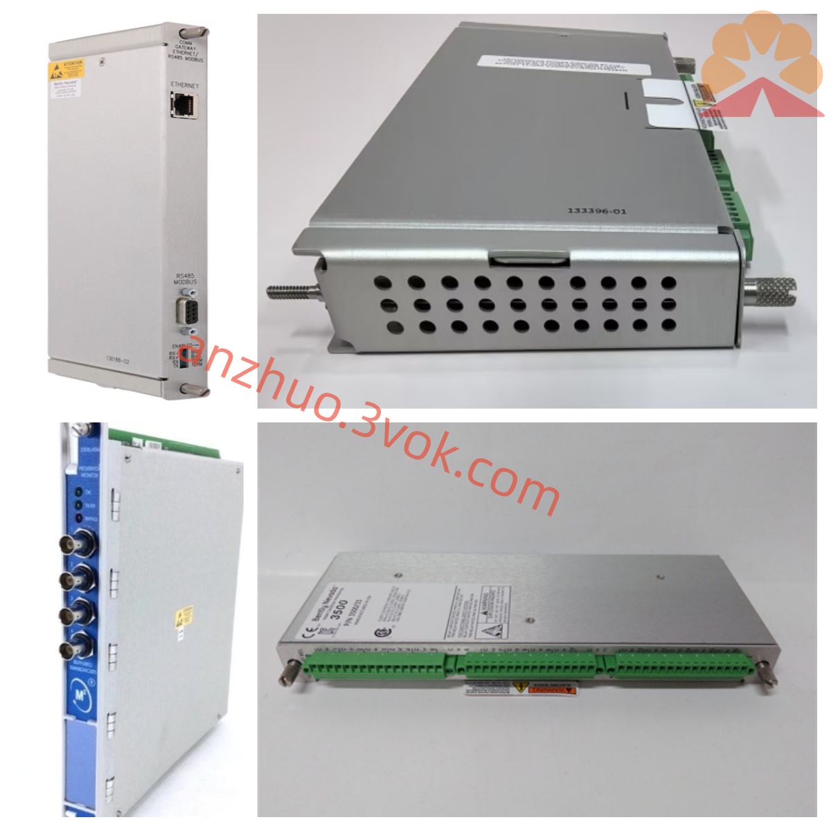
Bently Nevada 3300/55-01-04-03 Thrust Position Monitoring Module
Description
Bentley 3300/55-01-04-03 Dual-Channel Speed Vibration Monitoring Module (Comprehensive and Concise Description)
I. Product Overview
The Bentley 3300/55 is a dual-channel speed vibration monitoring module within the 3300 series TSI (Turbo-Supercharger Instrumentation) of Bently Nevada under Baker Hughes. It is used for online monitoring of absolute vibration speed of bearings and housings in rotating / reciprocating machinery.
Model 3300/55-01-04-03 represents the first three key configuration segments of the complete model, indicating:
01: Sensor sensitivity
04: Frequency response
03: Channel 1 range
This module is a 19-inch rack-mounted device, supporting hot swapping, and is compatible with the 3300 system backplane power supply and communication. It is widely used for vibration protection of steam turbines, compressors, fans, pumps, motors, etc. in non-explosion-proof areas of power plants, petrochemicals, metallurgy, etc.
II. Model Code Meaning (3300/55-01-04-03)
Complete model format: 3300/55–XX–XX–XX–XX–XX–XX–XX–XX–XX
For 3300/55-01-04-03:
3300: 3300 series TSI platform
55: Dual-channel velocity monitoring (Velocity Monitor)
01: Sensor sensitivity = 500 mV/in/s (highly sensitive Velomitor)
04: Frequency response = 10 Hz ~ 1000 Hz (-3 dB), covering mid-high frequency vibrations
03: Channel 1 range = 0–3.0 mm/s pk (velocity peak)
(The following digits are not given. The default standard configuration is: Channel 2 has the same range, no key signal, no analog output, standard relays, no additional communication, no special functions)
III. Core Functions
Dual-channel independent speed measurement
Two channels are completely isolated and synchronized sampling, compatible with Velomitor speed sensors (500 mV/in/s), measuring absolute vibration velocity peak. Suitable for capturing mid-high frequency faults such as bearing wear, gear meshing, and structural resonance.
Mid-high frequency band filtering
Standard frequency response 10 Hz–1000 Hz, high-pass / low-pass can be configured via jumper or software, filtering low-frequency interference and high-frequency noise, highlighting the characteristic frequency of faults.
High-precision signal processing
24-bit ADC, dynamic range >80 dB, accuracy ≤±1% reading, resolution 0.1 mm/s; can perform conversion between speed / acceleration / displacement (integration / differentiation).
Sensor and loop self-diagnosis
24-hour monitoring of sensor open circuit, short circuit, abnormal sensitivity, signal over-limit, distinguishing real vibration from loop faults, reducing false alarms.
Two-level alarm + relay output
Each channel has independent warning (Alert) / danger (Danger) thresholds, programmable delay 0–10 s; standard multi-channel SPST/SPDT relays are equipped, which can be directly connected to audible and visual alarms, unit interlocks, DCS/PLC.
Local display and configuration
Front panel with light bar meter and LED, real-time display of dual-channel vibration values, OK / alarm / fault status; keys can set the range, filtering, alarm threshold locally, without the need for a host computer.
System integration and anti-interference
Metal shielding, input / output / power isolation, common-mode anti-interference ≥2500 V AC; compatible with 3300 system bus and System 1 software, supports remote configuration, trend, storage, reports.
IV. Main technical parameters (corresponding to 01-04-03 configuration)
Channels: 2 independent isolation
Adapter sensor: Velomitor, 500 mV/in/s
Measurement range: 0–3.0 mm/s pk (Channel 1, Channel 2 same)
Frequency response: 10 Hz ~ 1000 Hz (-3 dB)
Accuracy: ≤±1% reading, resolution 0.1 mm/s
Sampling rate: 256 samples/second per channel
Alarm: 2 levels (alert / danger) per channel, delay 0–10 s
Power supply: -24 V DC (backplane power supply)
Power consumption: ≤3 W
Operating temperature: -30 ℃ ~ +65 ℃
Installation: 19-inch standard rack, hot-swappable
Explosion-proof: Non-explosion-proof, used in non-hazardous areas
V. Structure and Installation Key Points
Standard 19-inch module, metal panel + flame-retardant enclosure, shockproof and dustproof.
Back-end terminals: sensor input, relay output, power supply, system bus.
Support hot-swappable modules, no need to stop the entire TSI system for replacement.
Sensor installed at the rigid position of the bearing seat, single-ended grounding of the shielding layer to avoid interference.
VI. Typical Applications Thermal power: High-frequency vibration monitoring of turbine, feed pump, and induced draft fan bearing housings.
Petroleum and chemical industry: Vibration protection for compressors, turbines, and high-speed pump housings.
Metallurgy: Blast furnace fans, sintering main exhaust fans, motor vibration monitoring.
General industry: Online vibration protection and fault warning for large fans, pumps, and coal mills.
VII. Usage Notes
Only for use in non-explosion-proof areas.
Must be equipped with the original 500 mV/in/s Velomitor. Do not mix with other sensors of different sensitivities.
Do not disassemble or modify the circuitry or change the sensor calibration privately.
Alarm threshold and delay should be set according to the process of the unit to prevent false alarms or malfunctions.
Get a Quote