
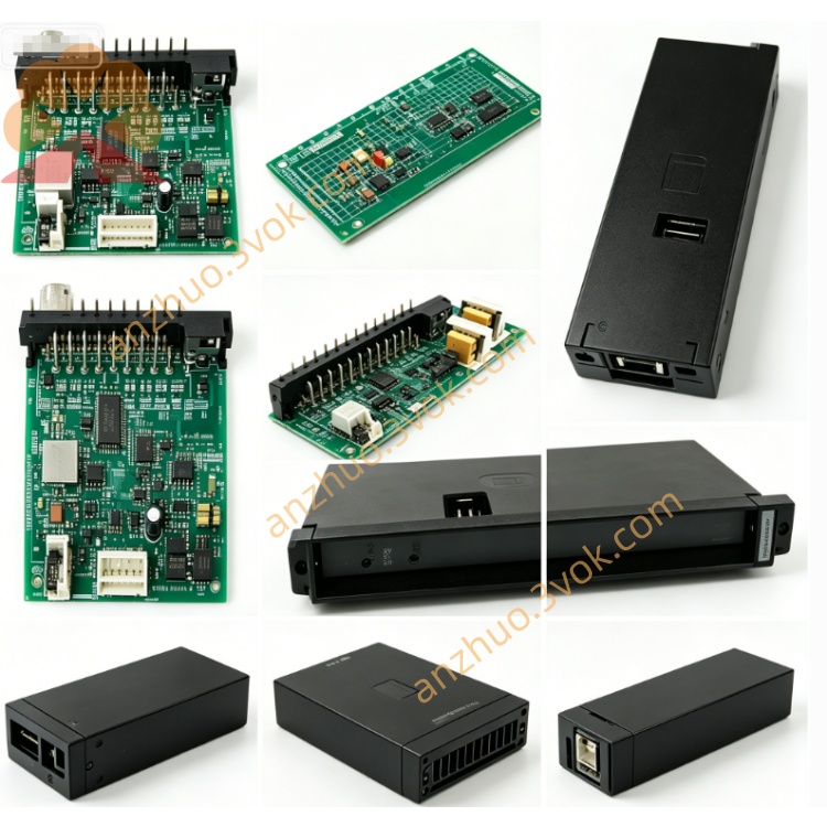
Reliance 418285-113A Drive Control Board
The 418285-113A is a PSBD-4A Gate Driver Interface / Power Connect Board manufactured by Reliance Electric (now part of ABB/Baldor). It is a legacy, obsolete printed circuit board (PCB) designed for the AutoMax and related high-power drive families, serving as the critical isolation and signal conditioning bridge between low-voltage control logic and high-power semiconductor switches (IGBT/MOSFET/SCR). Only refurbished, surplus, or used units are available for maintenance and replacement of aging industrial drive systems.
Description
Product Description
The 418285-113A is a PSBD-4A Gate Driver Interface / Power Connect Board manufactured by Reliance Electric (now part of ABB/Baldor). It is a legacy, obsolete printed circuit board (PCB) designed for the AutoMax and related high-power drive families, serving as the critical isolation and signal conditioning bridge between low-voltage control logic and high-power semiconductor switches (IGBT/MOSFET/SCR). Only refurbished, surplus, or used units are available for maintenance and replacement of aging industrial drive systems.
Model Number Interpretation
418285: Base part number for Reliance’s power interface and gate driver PCBs, dedicated to AutoMax and high-power drive platforms.
113A: Hardware revision and functional variant, specifying the PSBD-4A configuration with optimized isolation, gate drive pulse shaping, and fault monitoring circuitry for high-power converter applications.
Technical Specifications
It is a high-isolation, medium-power PCB engineered for Reliance AutoMax and legacy high-power drives. The board integrates gate drive transformers, opto-isolators, high-speed switching circuits, pulse amplifiers, and fault detection components. Physical dimensions are approximately 230mm × 160mm, with a weight of roughly 0.55kg. It operates from the drive’s 15–24V DC control supply, providing isolated gate pulses at up to ±15V for power semiconductor control, with isolation voltage rated at 2500V AC minimum. Designed for standard industrial temperature ranges (0°C to +60°C), it supports high-frequency switching up to 20kHz and includes overcurrent, overvoltage, and thermal protection circuits.
Interface and Communication Configuration
The board connects to the drive’s main control board via a 20-pin edge connector for low-level control signals and power. It interfaces with high-power semiconductor modules (IGBT/SCR) through dedicated screw terminals or high-current pin headers, delivering isolated gate drive pulses. Onboard test points and LED indicators (PWR, FAULT) enable status monitoring and troubleshooting. There is no digital communication port; all signals are analog/pulse-based with galvanic isolation between control and power domains. Installation is via slot-mounting in the drive’s power section, ensuring secure high-voltage connections.
Core Functions
Its core functions include galvanic isolation between low-voltage control circuits and high-power stages, protecting sensitive control electronics from high-voltage transients. It performs gate drive signal conditioning, converting 3.3V/5V logic pulses into high-current, isolated ±15V pulses to reliably switch IGBT/MOSFET/SCR devices. It provides fault detection and reporting, monitoring overcurrent, short-circuit, and overtemperature conditions in power semiconductors and sending fault signals back to the main controller. Additionally, it ensures high-frequency switching stability with integrated snubbers and noise filtering, reducing electromagnetic interference (EMI) in high-power converter systems.
Application Scenarios
It is primarily used in Reliance AutoMax series AC/DC high-power drives (50kW–500kW) for industrial motor control. It serves as a replacement part for other legacy Reliance drive models, including GV3000, MaxPak, and FlexPak high-power variants. Common deployment environments include steel mills, paper mills, cement plants, and mining operations relying on large-scale motor drives for production lines. It is essential for maintenance, repair, and retrofit projects of aging Reliance high-power drive systems, ensuring continued operation of critical industrial equipment.
Usage and Maintenance Instructions
Install the PCB into the designated slot in the drive’s power section, ensuring the edge connector is fully seated and all high-power terminals are torqued to specifications. Before powering on, verify all control and power wiring connections against the drive’s schematic to avoid reversed or loose connections. Conduct quarterly inspections to remove dust buildup from the board surface, check for cracked solder joints, bulging capacitors, or burned components, and confirm LED indicators function correctly. When servicing, always disconnect all AC/DC power sources and wait for high-voltage capacitors to fully discharge (minimum 15 minutes) to prevent electric shock hazards. Calibration of gate drive pulse timing should only be performed by qualified technicians using the official Reliance service manual procedures.
Get a Quote