
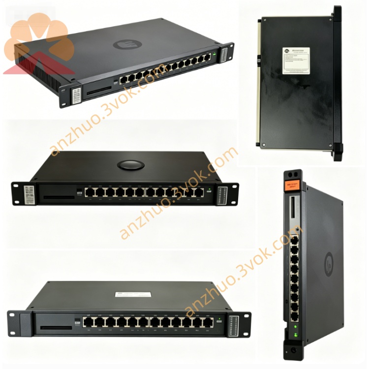
Reliance 45C40 Industrial PLC Control Module
Description
Product Introduction
45C40 (45C-40) is a dual-channel 115V AC/DC input module specifically for the Reliance (now ABB) AutoMate / AutoMax PLC system. It is used to collect two AC or DC switch quantity signals, compatible with common voltage levels in industrial sites. It has been discontinued and only refurbished, surplus, or NOS new products can be used for maintenance of the old system.
Model Interpretation
45C: Prefix of the Reliance AutoMate 45C series control component.
40: Represents a dual-channel 115V AC/DC input module.
45C40 = 45C-40: The hyphen is the industrial standard notation, and the two are exactly the same.
Without suffix: Standard hardware version, with fixed functions.
Technical Parameters
Module Type: Dual-channel AC/DC input module.
Input Channels: 2 independent inputs.
Rated Voltage: 115V AC/DC (compatible with 120V).
Frequency Range: 48–63Hz (AC).
Response Time: On conduction approximately 2.0ms, off approximately 19.0ms, typical 9.5ms at 60Hz.
Isolation Strength: Input - logic side 2500V, channel - channel 1000V.
Backplane Power Supply: 5VDC taken from the backplane of the 45C rack.
Size: Approximately 21mm×76mm×127mm.
Weight: Approximately 0.1kg.
Operating Temperature: 0°C to +55°C.
Adapter Rack: 45C1 standard I/O rail.
Compatibility: AutoMate 20/20E, AutoMax PLC, 45C series I/O rack.
Interface and Communication Configuration
Installation Method: Insert the 45C rack after power off, fix with screws, no hot swapping allowed.
Input Wiring: Connect 115V AC/DC switch signals to each channel, and the common terminal is connected together.
Status Indication: The panel contains a power (POWER) indicator light, which is always on when the power is normal.
Communication Interface: No independent communication port, data is exchanged with the PLC main control through the backplane bus.
Configuration Method: No DIP switches, the hardware is fixed to the 115V AC/DC input mode. Core function
Dual-channel signal acquisition: Can simultaneously connect two 115V AC or DC digital signals, suitable for scenarios involving both AC and DC power supplies.
Electrical isolation: High-voltage isolation between the input side and the PLC logic side, independent isolation between channels, anti-interference, surge protection and ground loop prevention.
Wide voltage compatibility: Supports a wide input range of 115V AC/DC, suitable for industrial standard voltage levels.
Fast response: Signal acquisition within milliseconds, suitable for real-time monitoring of conventional industrial digital signals.
Backplane bus communication: Through the 45C rack backplane for high-speed data interaction with the PLC, no additional wiring required. Applicable scenarios
Industrial switch quantity monitoring: 115V AC/DC limit switches, photoelectric sensors, relay contact signal acquisition.
Renovation of old equipment: Replace the aging modules of the same model in the AutoMate/AutoMax system to ensure the continuous operation of the old equipment.
Mixed AC and DC system: The control cabinet and production line signal acquisition have 115V AC and DC signals simultaneously.
General industrial control: Input of operation status and fault alarm signals of pumps, fans, valves and other equipment.
User and maintenance instructions
Before installation, all power supplies of the system must be cut off. Confirm that the backplane slots are clean and free of foreign objects. Insert and then tighten the fixing screws.
Use multi-strand copper wires for wiring. Tighten the terminals to prevent loosening. AC signals are recommended to use shielded lines, and the shield layer should be grounded at one end.
Before powering on, check that the wiring is correct. After powering on, the POWER light should be constantly on, without flickering or abnormal extinguishing.
Daily maintenance: Regularly check the tightness of terminals and the status of indicator lights, and keep the surface of the module clean without dust accumulation.
Fault troubleshooting: If the indicator light is not on, check the backplane power supply; if the signal is abnormal, check the wiring and input voltage; if isolation is damaged, replace the module.
Safety regulations: Before disassembling, maintaining or replacing, completely cut off the power supply. Do not operate with power on to avoid the risk of high voltage electric shock.
Get a Quote