
Reliance 418281-53A
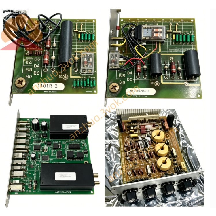
The 418281-53A is a TST-1 test and signal conditioning printed circuit board (PCB) manufactured by Reliance Electric, a legacy brand under ABB/Baldor. It functions as a dedicated auxiliary control board for older drive systems, focused on analog signal processing, drive testing, and calibration. This part is obsolete and no longer in production; only refurbished, surplus, or used units are available for maintenance and replacement of legacy industrial drive equipment.
Description
Product Description
The 418281-53A is a TST-1 test and signal conditioning printed circuit board (PCB) manufactured by Reliance Electric, a legacy brand under ABB/Baldor. It functions as a dedicated auxiliary control board for older drive systems, focused on analog signal processing, drive testing, and calibration. This part is obsolete and no longer in production; only refurbished, surplus, or used units are available for maintenance and replacement of legacy industrial drive equipment.
Model Number Interpretation
418281: The base part number designating it as a member of Reliance’s TST-series test and signal PCBs, specifically engineered for VVT2 and related drive platforms.
53A: Denotes the hardware revision and functional variant, corresponding to the standard TST-1 configuration with specific component layouts and calibration circuitry for signal conditioning and drive diagnostics.
Technical Specifications
It is a low-power, low-voltage signal processing PCB designed exclusively for Reliance legacy drives, including the VVT2, GV3000, and MaxPak series. The board integrates analog circuitry such as operational amplifiers, precision potentiometers for gain and offset adjustment, signal transformers, and passive components for filtering and scaling. It is constructed as a slot-mounted PCB with edge connectors for direct insertion into dedicated slots within the drive cabinet. The physical dimensions are approximately 220mm × 150mm, with a weight of roughly 0.2 to 0.3 kilograms. It operates on low-voltage control power from the drive, designed for stable performance within standard industrial temperature ranges, and is not intended for high-power or high-voltage applications.
Interface and Communication Configuration
The board connects to the drive’s internal control and power circuits via onboard edge connectors and pin headers, serving as the primary interface for collecting raw analog signals (voltage, current, speed) from the drive’s power stage. Processed analog signals are output through hardwired terminals to panel meters, external monitoring devices, or the drive’s main control board. There is no digital communication interface; all signal transfer relies entirely on analog wiring and physical contact. Installation is limited to the dedicated PCB slot in the drive chassis, ensuring secure and reliable electrical and mechanical connections.
Core Functions
Its core functions include analog signal conditioning, where it filters electrical noise, scales signal levels, and corrects offset errors to ensure accurate and stable analog signals. It supports drive system testing and calibration, enabling precise adjustment of voltage, current, and speed signals for both offline bench testing and online operational calibration. It aids in fault diagnosis by providing test points and conditioned signals to troubleshoot issues in the drive’s control loop or power unit. Additionally, it acts as a critical spare part for maintaining aging Reliance drive systems, ensuring continued operation of legacy equipment.
Application Scenarios
It is primarily applied to Reliance VVT2 series AC drives as a standard signal conditioning and test board. It is also used for repair and replacement in other legacy Reliance drive models, including GV3000, MaxPak, FlexPak, and related DC drive systems. Common deployment environments include manufacturing plants, paper mills, textile factories, and metal processing facilities that rely on older Reliance drive equipment for production lines. It is essential for routine maintenance, system upgrades, and emergency part replacements in industrial automation systems with installed legacy Reliance drives.
Usage and Maintenance Instructions
Install the PCB into the designated slot within the drive cabinet, ensuring the edge connectors are fully inserted and locked in place to avoid loose connections. Before powering on, verify all internal signal wiring connections against the drive’s schematic diagrams to confirm firm and correct terminations. Conduct regular quarterly inspections to remove dust buildup from the board surface and check for loose pins, damaged components, or signs of aging such as corrosion or burned circuitry. When disassembling or servicing the board, always disconnect all power sources from the drive and wait for internal capacitors to fully discharge to prevent electric shock hazards. Calibration of potentiometers should only be performed by qualified technicians following the official Reliance service manual procedures.
Get a Quote