
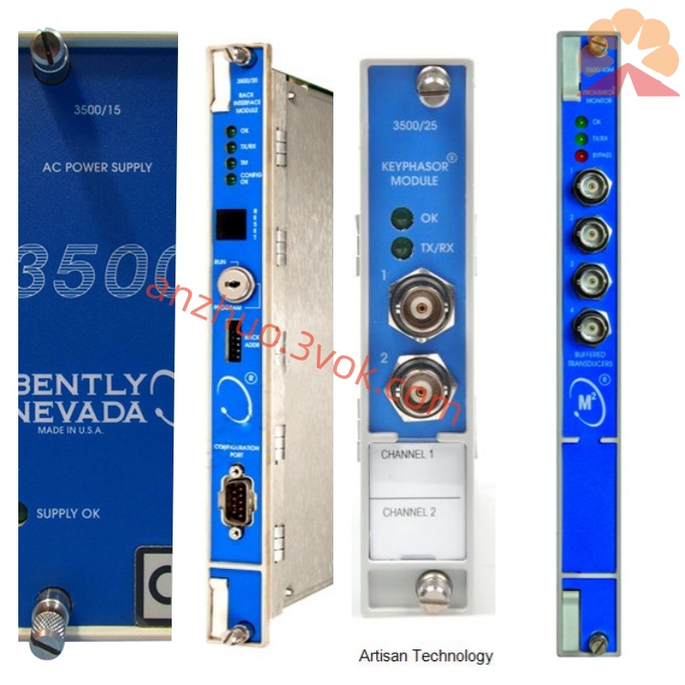
Bently Nevada 3300/80-01-01-00-00 Relay Output Module
Description
Bentley 3300/80-01-01-00-00 Dual-Channel Vibration Monitoring Module - Detailed Product Description
I. Product Overview
The Bentley 3300/80-01-01-00-00 is a standard dual-channel vibration monitoring module of the TSI turbine monitoring instrument system under the brand of Baker Hughes, Nevada. It adopts a rack-mounted modular design and supports hot-swappable modules. This module is specifically developed for radial shaft vibration monitoring of rotating machinery and is compatible with the 3300 XL series 5mm eddy current sensing system. It has functions such as signal acquisition, self-diagnosis of faults, multi-level alarms, and relay interlock output. The overall performance complies with the API 670 industry standard. The product operates stably and has strong anti-interference capabilities. It is mainly used in ordinary non-explosion-proof areas of industries such as power, petrochemicals, and metallurgy. It is equipped with equipment such as steam turbines, small compressors, generator sets, and large pump sets to achieve online vibration monitoring, fault early warning, and safety shutdown protection.
II. Model Code Interpretation
3300: This is the classic 3300 series modular TSI system of Bentley. It is installed in a standard 19-inch cabinet rack and supports multi-module combination expansion, centralized power supply, and hot-swappable module replacement.
80: Function code, representing a dual-channel vibration monitoring module, equipped with two completely independent signal input channels, specifically for the measurement of the radial shaft vibration of equipment.
01: Input specification code, the module matches the 3300 XL series 5mm eddy current probe, extension cable, and preamplifier, suitable for small-scale measurement point installation scenarios.
01: Range and sensitivity configuration, the standard vibration range is 0-2 mm peak-to-peak, corresponding to the system's standard sensitivity, meeting the vibration monitoring requirements of small and medium-sized units.
00: Frequency response configuration, the effective frequency response range is 1-800 Hz, suitable for low-speed and medium-speed rotating equipment, capable of fully capturing the rotor's fundamental frequency, harmonic frequencies, and other fault characteristic signals.
00: Output and additional function configuration. This model does not have an analog output interface. It only retains relay alarms, status indicators, and basic configuration functions, without any additional custom expansion functions.
III. Core Functions
Dual-channel independent vibration monitoring. The two channels' circuits are completely isolated, and they do not cause signal interference with each other. They can simultaneously perform continuous real-time vibration measurement on two radial measurement points of the equipment. A single module can achieve dual-point monitoring, effectively saving rack installation space.
Built-in OK fault self-check circuit, monitoring the working status of the probe, extension cable, and preamplifier at all times. It can accurately identify abnormal situations such as sensor circuit breakage, short circuit, and signal over-limit, clearly distinguish mechanical body faults from sensor component faults, effectively reducing the probability of false alarms and false interlocks in the field.
Multi-level alarms and interlock control. Each channel can independently set warning and danger threshold values. The alarm delay supports programming adjustment. It can filter out instantaneous signal fluctuations that cause false actions. Each channel is equipped with two passive relay contacts. The entire system has a total of four alarm contacts, which can be directly connected to the on-site sound and light alarm circuits and the safety shutdown interlock circuits of the unit.
High-precision signal processing, equipped with mature signal conditioning and linearization circuits. The measurement linearity is excellent, capable of stably capturing typical mechanical faults such as rotor imbalance, shaft misalignment, contact and wear between moving and stationary parts, and deterioration of bearings.
Local status display and basic configuration. The panel is equipped with multiple groups of LED status indicator lights, allowing for intuitive viewing of module operation status, channel status, warnings, dangers, bypass, etc.; combined with operation keys, it can complete basic parameter settings and alarm logic configuration on-site.
All-round anti-interference design. Internal electromagnetic shielding structure is set up. The input, output, and power supply circuits are electrically isolated from each other. It can withstand electromagnetic interference generated by industrial equipment such as frequency converters, high-power motors, and high-voltage equipment, ensuring the long-term stability of measurement signals in complex working conditions.
IV. Technical Parameters
Measurement Parameters
The module consists of two independent measurement channels. The standard vibration measurement range is from 0 to 2 millimeters peak-to-peak. It is compatible with a 5mm eddy current probe with a standard linear working range. The overall measurement linear error is no more than ±0.5% of the full scale, and the minimum measurement resolution is 0.01 millimeters. The frequency response range is from 1 to 800 hertz, covering the vibration frequency range of most medium and low-speed rotating equipment. The alarm delay can be programmed within the range of 0 to 10 seconds. The factory default delay is 3 seconds. Electrical parameters
Module operating power supply is -24 volts DC, with a voltage fluctuation range of ±10%. The maximum operating power consumption of the entire machine does not exceed 2.5 watts. The input circuit is matched with a 3300 XL 5mm eddy current preamplifier, and the input impedance complies with the unified standard of the system. This model does not have analog voltage or current output functions. The relay output is an inductive contact without power, with a rated load of 250 volts AC and 3 amperes for a single contact, which can directly drive alarm devices and interlock circuits. The module supports internal bus communication of the 3300 system and can be integrated into the entire monitoring system for centralized management. The input, output, and power supply have high-voltage electrical isolation capabilities, and have good anti-common-mode interference performance.
Environmental and mechanical parameters
The normal operating temperature range of the equipment is -40 degrees Celsius to +70 degrees Celsius, and the storage temperature range is -40 degrees Celsius to +85 degrees Celsius. The relative humidity of the working environment is 0% to 95%, and condensation is prohibited inside the environment. It is installed in the standard rack slot of the 3300 series, supports hot swapping, and the module can be disassembled, replaced, and installed without power interruption of the system. The enclosure is made of metal panels combined with flame-retardant engineering plastics, with characteristics of shock resistance, corrosion resistance, and oil resistance. The overall protection level is IP20, suitable for installation in the control cabinet.
Certification and compliance requirements
The product has CE electromagnetic compatibility certification, meeting the usage specifications for industrial sites with electromagnetic environments. The design and manufacture strictly follow the API 670 standard for rotating machinery monitoring and protection. This module has no explosion-proof structure, does not have a built-in safety barrier, and can only be used in non-flammable and non-explosive industrial areas.
V. Structural Design
The module as a standard rack modular structure is divided into three parts: the front panel, the internal main circuit, and the rear wiring terminals. The front panel integrates status indicator lights and operation buttons, allowing operators to view the running and alarm status on-site, complete basic parameter configuration, and operate simply and intuitively. The internal main circuit is divided into two completely independent signal processing units, corresponding to two measurement channels. Each unit integrates signal conditioning, filtering, fault detection, and alarm comparison functions circuits, with strong channel independence and low operating failure rate. The rear wiring terminals are arranged in zones, clearly dividing two channels of probe input terminals, four channels of relay alarm terminals, as well as power and system communication interfaces. The wiring is neat, facilitating on-site wiring, inspection, and fault troubleshooting. The module supports hot swapping, and replacing the module does not require shutting down the entire monitoring system, reducing the impact of maintenance work on the normal operation of the unit.
VI. System Compatibility
Hardware-wise, this module can fully adapt to the 3300 series standard rack, system power module, and system monitoring module. Different functions of modules in the same series can be installed in the same rack for collaborative work. The entire machine is compatible with 3300 XL series 5mm eddy current probes, extension cables, and preamplifiers. Components of the same specification can be directly interchanged without recalibration. Relay contacts can be connected to on-site sound and light alarms and unit safety interlock circuits. Software-wise, it is compatible with the Bechtel supporting configuration software and System 1 equipment status monitoring software, enabling remote parameter configuration, real-time data collection, trend analysis, fault record storage and query, and centralized management of the entire unit monitoring data after connecting to the system bus.
VII. Typical Application Scenarios
In the power industry, it is mainly used for radial vibration monitoring and over-limit protection of small and medium-sized steam turbines in thermal power plants, auxiliary power generation units, large feedwater pumps, and other equipment in auxiliary facilities, ensuring the stable operation of auxiliary equipment. In the petrochemical industry, it is applied in small and medium-sized centrifugal compressors, process pumps, and auxiliary turbine equipment in non-explosion-proof areas, real-time monitoring of vibration status, and early prevention of rotor faults causing shutdowns. The metallurgical industry is suitable for large fans, drive motors, and auxiliary transmission equipment of rolling mills. Through vibration monitoring, potential problems such as bearing wear and rotor imbalance can be predicted. It can also be applied to various medium and large-sized rotating machinery in general industrial fields such as cement, papermaking, and light industry, for online condition monitoring, preventive maintenance, and safety interlock protection.
VII. Installation and Maintenance Specifications
Installation Requirements
Insert the module smoothly into the vacant slot of the 3300 rack, ensuring that the rear connector is fully in contact. Tighten the fixing screws of the panel. Connect the two 5mm eddy current preamplifier signal cables to the corresponding input terminals according to the channel number, ensuring a firm and secure connection without loosening. Connect the relay contact lines to the alarm circuit or the unit interlock circuit according to the design plan. After confirming that the rack power supply is normal, power on. Use the panel buttons or remote configuration software to set the vibration alarm threshold, alarm delay, etc., according to the requirements of the on-site equipment. Save and take effect after setting. The installation of the probe must strictly follow the specifications. Set the static installation gap of the 5mm eddy current probe according to the standard value. Ensure that the probe end face is perpendicular to the surface of the measured shaft, and fix the probe cable well to avoid cable wear or breakage due to equipment operation vibration.
Daily Maintenance
During daily inspections, regularly observe the status of the panel indicator lights to confirm that the module and each channel are operating normally. At the same time, check for any looseness, oxidation, or overheating at all connection terminals. Regularly use a standard gap calibration device to calibrate the measurement accuracy of the module according to the design plan to ensure that the measurement data meets the technical standards. Regularly clean the surface of the module and the internal dust of the rack slot to ensure good ventilation and heat dissipation of the module, and prevent dust accumulation from causing poor heat dissipation and short circuits. When replacing spare parts, it is necessary to use the original Bentley module, probe, and matching cables of the same model. Do not use non-original accessories.
IX. Usage Precautions
This module has no explosion-proof structure or built-in safety barrier. It is strictly prohibited to install and use it in flammable and explosive, or areas with combustible gases or dust. It must be used in conjunction with the 3300 XL 5mm standard eddy current sensing system. Do not mix 8mm, 11mm, etc. other specifications of probes. Otherwise, there will be a mismatch in range and sensitivity, resulting in measurement failure. The static installation gap of the probe must be strictly executed according to the equipment specifications. Too small a gap is likely to cause wear and damage between the shaft and the probe, while too large a gap will result in insufficient signal strength and decreased measurement linearity. Do not disassemble the module, modify the internal circuit, or change the factory-calibrated length of the sensing cable without authorization. Illegal operations will cause equipment damage and loss of product warranty rights. Before conducting wiring, maintenance, or module replacement operations, it is necessary to cut off the power supply of the rack to prevent short circuits and electric shock accidents. The alarm threshold, delay, etc. must be set strictly according to the process requirements of the unit. Inappropriate parameters will cause protection failure or frequent false alarms. The installation position of the module should be as far away as possible from power frequency converters, transformers, high-voltage distribution cabinets, etc., which are strong electromagnetic interference sources, to reduce the impact of external interference on the measurement signal.
Get a Quote