
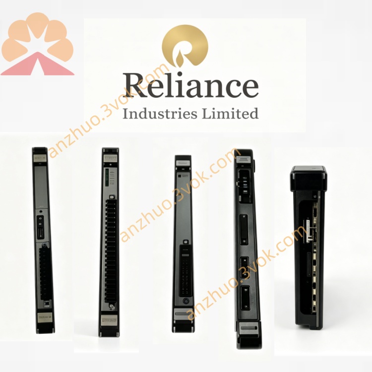
Reliance 140CM21A
Description
Product Description
Model Definition
140: Indicates the series and physical size classification of the interface module.
C: Represents the product category, designating it as a control/interface module for drive systems.
M: Stands for "module," identifying it as a standalone electronic assembly.
21: Denotes the specific configuration and functional variant, including switching output and LED indication for DC bus and braking current.
A: Signifies the revision level of the module’s hardware and circuitry.
Technical Specifications
DC Bus Voltage Monitoring: Triggers left LED when DC bus voltage (UDC) exceeds 50 V.
Braking Current Monitoring: Triggers right LED when braking current (IB) exceeds the preset threshold.
Switching Output: Wearless transistor switch between terminals 1 (negative) and 2 (positive), rated for low voltage and current applications.
Operating Voltage: Compatible with Reliance drive system control voltage (typically 24 VDC logic supply).
Environmental Rating: Designed for industrial use, operating temperature range 0 °C to +50 °C.
Construction: Compact printed circuit board (PCB) assembly with metal mounting bracket for panel installation.
Weight: Approximately 0.5 kg.
Status Indicators: Two LED indicators for DC bus voltage and braking current status.
Interface and Communication Configuration
Power Interface: Connects to the drive’s internal 24 VDC logic power supply via dedicated terminals.
Signal Inputs: Monitors DC bus voltage and braking current directly from the drive’s power circuitry.
Switching Output: Provides a single transistor-based switch output (S1-2) for triggering external relays, alarms, or interlocks when DC bus voltage exceeds 50 V.
Mounting Interface: Metal bracket for secure panel mounting, compatible with standard industrial control panel dimensions.
Compatibility: Designed exclusively for Reliance Electric DC drives (e.g., MinPak Plus, FlexPak Plus) and AC drive systems, with no independent communication port; all signals are processed locally and interfaced directly with the host drive.
Core Functions
DC Bus Voltage Monitoring: Continuously tracks the drive’s DC bus voltage and activates an LED indicator when the voltage exceeds 50 V, aiding in system diagnostics.
Braking Current Monitoring: Monitors the drive’s braking current and triggers an LED when the current exceeds the threshold, enabling early detection of braking circuit issues.
Isolated Switching Output: Provides a wearless transistor switch output for external interlocking or alarm functions, eliminating mechanical contact wear and ensuring long-term reliability.
Local Status Indication: Integrated LEDs allow on-site visual monitoring of critical drive parameters without external tools.
Signal Isolation: Electrical isolation between the drive’s high-power circuitry and low-voltage control signals protects external devices from voltage spikes.
Application Scenarios
Reliance DC Drive Systems: Used with MinPak Plus and FlexPak Plus DC drives for monitoring DC bus voltage and braking current.
Legacy Industrial Automation: Ideal for maintenance and retrofitting older Reliance drive systems in manufacturing, metalworking, and material handling industries.
Panel Mounted Control Systems: Installed in industrial control panels to provide local status indication and switching functions for drive systems.
Braking System Monitoring: Applied in systems with dynamic braking to monitor braking current and prevent overheating or component failure.
Interlock and Alarm Systems: Used to trigger external alarms or interlocks when DC bus voltage exceeds safe levels, enhancing system safety.
Usage and Maintenance Instructions
Usage
Installation: Mount the module securely on a rigid panel using the metal bracket, ensuring adequate ventilation around the unit.
Wiring: Connect the 24 VDC power supply, DC bus voltage sense wires, braking current sense wires, and switching output cables strictly according to terminal labeling.
Configuration: No user configuration is required; the module operates automatically once wired correctly.
Commissioning: After wiring, power on the drive system and verify LED operation: left LED illuminates when DC bus >50 V, right LED illuminates during braking current flow.
Integration: Connect the switching output (S1-2) to external relays or alarms as needed for interlock functions.
Maintenance
Regular Inspection: Every 3–6 months, check the PCB, terminals, and wiring for corrosion, loose connections, or physical damage.
Cleaning: Disconnect power before cleaning; use a dry cloth to wipe the module surface and remove dust, avoiding moisture or chemical cleaners.
Terminal Tightening: Annually retighten all wiring terminals to prevent loose connections that may cause signal errors.
LED Check: Verify LED functionality during routine drive maintenance to ensure accurate status indication.
Replacement: If the module fails to operate or shows persistent LED errors, replace it with a refurbished or new unit; do not attempt to repair the PCB as it contains static-sensitive components.
Storage: Keep spare modules in a cool, dry, static-free environment, stored in anti-static bags to prevent damage.
Get a Quote