
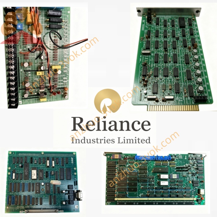
Reliance 404TSD
Description
Product Description
Model Number Interpretation
404: Core series identifier for Reliance’s high‑density digital I/O modules, targeted at AutoMax distributed control systems.
T: Indicates Terminal block interface for field wiring.
SD: Denotes Sink/Source input type compatibility (24 VDC wet contact or dry contact).
Technical Specifications
Channel Count: 32 isolated digital input channels.
Input Voltage: 24 VDC (operating range: 15–30 VDC).
Input Current: 3.5 mA typical at 24 VDC.
Response Time: <10 ms (configurable hardware filtering).
Isolation: Group‑wise optical isolation (8 channels per group); field‑to‑system isolation.
Operating Temperature: 0 °C to +60 °C.
Storage Temperature: ‑40 °C to +85 °C.
Humidity: 5%–90% non‑condensing.
LED Indicators: Per‑channel ON/OFF status; module OK/fault LED.
Mounting: Standard AutoMax S‑RACK I/O rack (backplane‑mounted).
Hot‑Swap: Supported (system‑configuration dependent).
Protection Rating: IP20 (for cabinet installation).
Interface & Communication Configuration
Field Interface: Screw‑terminal block for direct connection to dry contacts (limit switches, pushbuttons) or 24 VDC wet contacts (sensors, relays).
Backplane Interface: AutoMax proprietary backplane bus for high‑speed communication with the main processor (e.g., 57C331 CPU).
Communication Protocol: No native Ethernet; relies on backplane bus for data exchange with the AutoMax DCS network.
Diagnostic Interface: Front‑panel LED indicators for channel status and module health; no external diagnostic port.
Core Functions
High‑Density Signal Acquisition: Captures 32 discrete on/off signals from field devices, converting them to logic‑level data for the controller.
Fault Isolation: Group‑wise isolation limits short‑circuit impacts to 8 channels, preventing system‑wide failures.
Noise Filtering: Configurable hardware filtering suppresses contact bounce and electrical interference for stable signal readings.
Status Monitoring: Per‑channel LEDs enable quick visual verification of input states; module OK LED confirms healthy operation.
Legacy System Integration: Seamlessly integrates with AutoMax programming software (Logic Builder/System Manager) for automatic address mapping and logic access.
Application Scenarios
Legacy AutoMax DCS Systems: Primary digital input module for Reliance AutoMax platforms in power plants, water treatment facilities, and manufacturing sites.
Heavy Industry: Steel mills, paper mills, and chemical plants for monitoring valve positions, motor status, and safety interlocks.
Process Automation: Conveyor systems, packaging machinery, and assembly lines requiring high‑density discrete signal monitoring.
Legacy Equipment Maintenance: Direct replacement for aging S‑D4043/404TSD modules to extend the service life of AutoMax systems.
Usage & Maintenance Instructions
Installation: Insert into a designated slot in the AutoMax S‑RACK; ensure the backplane connector is fully seated and secured with rack screws.
Wiring: Connect field devices to the screw terminals per the system schematic; verify wiring polarity and tightness to avoid loose connections.
Configuration: Use AutoMax programming software to assign input addresses and configure filtering parameters; download the configuration to the module.
Operation: Apply power and verify the module OK LED is lit; check per‑channel LEDs for correct input status during normal operation.
Routine Maintenance: Quarterly inspections to clean dust from the module surface and terminals; verify LED functionality and backplane connection integrity.
Safety: Disconnect all power to the rack before installation/removal; discharge capacitors fully to prevent electric shock. Adhere to lockout/tagout procedures during maintenance.
Get a Quote