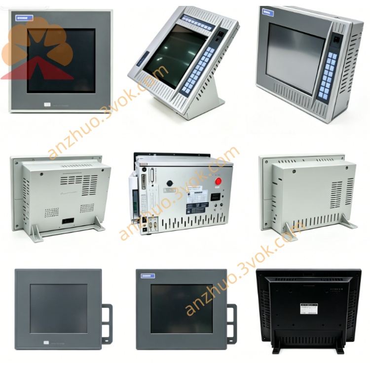
XYCOM XVME-240 Detailed Product Description
Description
XYCOM XVME-240 Detailed Product Description
I. Product Overview
XVME-240 is a 6U dual-high VMEbus high-density TTL digital input/output module launched by XYCOM (now affiliated with Acromag/Xembedded). It focuses on 80 TTL-level I/O (8×10-bit ports), targeting high-density switch quantity acquisition and high-speed control output in industrial fields, and is compatible with VME architecture measurement, automation, and testing systems. This module has been officially discontinued, and the market circulation is mainly in the form of second-hand, refurbished, and inventory spare parts. The standard order number is 70240-001.
Core Positioning
As a VMEbus slave device, XVME-240 focuses on "high-density TTL I/O + byte-level configurable + low latency + interrupt-driven", with 80 channels integrated per slot, supporting independent setting as input or output for each port, suitable for scenarios without electrical isolation and emphasizing high-speed parallel signal processing, widely used in the maintenance and upgrade of old VME systems and high-density measurement control nodes.
II. Core Functional Characteristics
1. Standard VMEbus Interface (fully compatible design)
Fully complies with IEEE 1014 VMEbus specification, compatible with all 6U VME chassis and backplanes, operating in slave device mode. The address space supports A16 (64KB), fixed occupying 1KB address window, the base address is flexibly configured within 1KB boundary through onboard jumpers to avoid address conflicts. Data width is compatible with D08/D16, compatible with 8/16-bit VME master controllers. Backplane connection requires P1+P2 connectors, compatible with dual-high module standard, supports VME interrupts (configurable priority), meeting real-time response requirements.
2. 80 High-Density TTL I/O Channels (core function)
Provides 80 independent TTL-level channels, divided into 8 10-bit ports, each port can be independently configured as input or output through software, flexibly adapting to mixed signal scenarios.
Input Characteristics: TTL compatible (high ≥ 2.4V, low ≤ 0.4V), input impedance 10kΩ, supports single-ended signal acquisition, maximum sampling rate 1MHz/ channel, compatible with sensors, limit switches, encoders, etc. digital signals.
Output Characteristics: TTL push-pull output, high ≥ 2.4V, low ≤ 0.4V, single channel maximum load 20mA, can directly drive TTL loads, small relays, indicators, or as synchronous trigger signals, integrated short-circuit protection to avoid module damage due to load faults.
Group Management: By byte/port grouping, supports batch reading and writing and bit operations, simplifies programming and improves data throughput efficiency.
3. Interrupt and Real-time Response Capability
Supports input status change interrupts (rising edge / falling edge / bilateral edge configurable), can shield any channel interrupt, compatible with critical signal real-time alarm and synchronous control. When interrupt triggered, sends a request to the VME master controller to achieve microsecond-level response, suitable for fault detection, safety interlock, and high-precision synchronization scenarios.
4. Low Latency and High-Speed Data Throughput
TTL circuit low-latency design, channel response time ≤ 100ns, supports high-frequency signal acquisition and high-speed control output, meeting high real-time requirements in scenarios such as automation testing, motion control, etc. High bus data transmission rate, supports byte/word/block transmission, high batch I/O refresh efficiency.
5. Industrial-grade High Reliability Design Standard working temperature: 0℃ to +65℃; storage temperature: -40℃ to +85℃; humidity: 20%–80% RH (non-condensation); suitable for harsh environments such as industrial sites, outdoor and test equipment. Resistance to vibration: 5–2000Hz, 1.0g; resistance to shock: 30g (operational state); complies with MIL-STD-810G standards, suitable for equipment operation vibration scenarios. EMC compliance (CE/FCC Class A), multi-layer board wiring and gold-plated gold fingers design, reduces electromagnetic interference, stable operation over the long term.
6. Panel status indicator lights
The front cover is equipped with POWER, RUN, CH0–CH79 ACT indicator lights: POWER constantly on indicates normal +5V power supply; RUN constantly on indicates self-check passed and module normal operation; CH ACT lights up when the corresponding channel input/output is valid, facilitating rapid on-site channel status troubleshooting.
III. Hardware Specifications Details
Bus interface specifications
Bus protocol: IEEE 1014 VMEbus, slave device mode;
Address space: A16 (64KB), 1KB window, jumper configuration base address;
Data width: D08/D16;
Interrupt support: VME interrupt, configurable priority and trigger mode;
Backplane interface: P1+P2 connectors;
Size: 6U (160mm×233.4mm), single slot;
Weight: approximately 0.7kg.
I/O channel specifications
Channel quantity: 80 TTL I/O (8×10-bit ports, ports can be configured as input/output);
Input level: TTL (high ≥ 2.4V, low ≤ 0.4V);
Input impedance: 10kΩ;
Maximum sampling rate: 1MHz/channel;
Output level: TTL (high ≥ 2.4V, low ≤ 0.4V);
Output drive: 20mA/channel (sourcing/drain current);
Response time: ≤ 100ns;
Protection mechanism: output short circuit protection, overcurrent protection;
Interrupt characteristics: edge-triggered input (rising/falling/double-edge), supports interrupt masking.
Electrical and environmental specifications
Power supply: +5V DC ±5%, typical current 1.2A (approximately 6W);
Working temperature: 0℃ to +65℃;
Storage temperature: -40℃ to +85℃;
Resistance to vibration: 5–2000Hz, 1.0g;
Resistance to shock: 30g (operational)/50g (non-operational);
Humidity: 20%–80% RH (operational)/20%–90% RH (non-operational), non-condensation;
Altitude: maximum 3048m (operational)/12192m (non-operational).
IV. Typical Application Scenarios
1. Industrial automation high-density switch quantity control
Suitable for electronic assembly, semiconductor equipment, packaging machinery production lines, collecting a large number of sensors, limit switches, photoelectric signals, driving solenoid valves, indicator lights, small contactors, 80 channels meet the high-density node requirements, TTL level compatible with internal digital signal interaction of equipment.
2. Automated testing and measurement system
Used for functional testing, ATE testing platform, collecting test fixture status signals, triggering test processes, output control signals, low latency and high-speed sampling capability is suitable for high-frequency testing scenarios, interrupt function realizes test synchronization and rapid fault response.
3. Motion control and synchronous triggering system
Suitable for multi-axis motion control, output pulse/direction signals drive stepper/servo drivers, collecting encoder zero position, limit signals, 80 channels can simultaneously handle multi-axis control and status feedback, TTL level ensures high-speed synchronization accuracy.
4. Upgrade and replacement of outdated VME systems
Directly replace the insufficient channels or slow-speed I/O modules in the old system without modifying the chassis structure and main program, and upgrade to 80 high-density, high-speed TTL I/O, suitable for the maintenance of old VME devices in military, aerospace, and industrial control fields, and extend the equipment lifespan.
5. Laboratory and Instrument Measurement and Control System
Used for laboratory instruments and data acquisition systems, it collects instrument status, trigger signals, and synchronization clocks, and outputs control instructions. The high channel density is suitable for parallel measurement and control of multiple instruments, and the low latency improves test efficiency and data accuracy.
VII. Installation and Programming Key Points Installation steps
Preparations: Ensure that the P1/P2 slots of the VME chassis are intact and the +5V power supply is stable; Prepare TTL level shielded cables, and for long-distance wiring, prefer differential shielded cables.
Jumper configuration: Set the A16 base address jumper to avoid address conflicts; Configure the interrupt priority jumper (if interrupts are needed).
Module insertion: Align the XVME-240 to the 6U slot and push it in smoothly to ensure that the gold fingers make good contact with the backplane, and tighten the panel screws.
Connection wiring: Connect the input channels to TTL sensors/sensors, the output channels to TTL loads or small relays, and the common terminal to the signal ground; Connect the shield layer in single-ended mode and keep it away from strong interference equipment such as frequency converters and motors.
Power-on self-test: After the chassis is powered on, the POWER and RUN indicator lights are constantly on, and all CH ACT are off; During software testing of input/output, the corresponding ACT indicator light is on, indicating that the module is normal.
Programming flow (simplified)
Address mapping: Configure the A16 base address, map the control, data, interrupt, and mask registers to the system memory to establish communication between the CPU and the module.
Port configuration: Write the configuration word to the control register to set 8 10-bit ports as input or output.
Input acquisition: Read the input data register to obtain the status of 80 channels, supporting byte/word/bit reading.
Output control: Write control data to the output data register to control the channel output level bit by bit, supporting batch or single-point control.
Interrupt configuration: Set the interrupt trigger edge, enable interrupts, configure the mask register, and write the interrupt service program to handle status change events.
Reset operation: When the system/software is reset, the module clears the output, disables interrupts, and clears flags to ensure safety.
Six. Core advantages
1. 80 high-density TTL I/O, maximum channels per slot
80 independent channels, 8 ports can be flexibly configured as input/output, balancing density and flexibility, no need for multi-module expansion, saving slots and costs.
2. High speed and low latency, strong real-time performance
TTL circuit response ≤ 100ns, 1MHz high-speed sampling, suitable for high-frequency signal acquisition and high-speed control output, meeting real-time measurement and control requirements.
3. Flexible interrupt-driven, fast event response
Input edge-triggered interrupt, configurable priority and mask, critical signals respond in microsecond level, suitable for fault alarm and synchronous control scenarios.
4. Industrial-grade reliability, stable in harsh environments
Wide temperature, shock-resistant, impact-resistant design, EMC compliance, suitable for industrial, outdoor, and testing environments, stable long-term operation, low maintenance costs.
5. Standard VME bus, easy integration and upgrade
Fully compatible with VMEbus specifications, directly compatible with existing 6U VME systems; simple configuration, convenient wiring, supports upgrading of old systems and building new systems, strong compatibility.
Seven. Notes
The module has been discontinued. When purchasing, prefer to choose second-hand/reconditioned spare parts with complete test reports, check the model 70240-001 and version, to avoid faulty or incompatible modules.
The channels are TTL level,严禁 connecting high-voltage signals (≥12V), otherwise burn the input/output circuit; external signals need to strictly match the TTL level standard.
The maximum load of the output channel is 20mA,严禁 driving large power loads; when driving inductive loads, it is necessary to parallel a shunt diode (such as 1N4007) to protect the output channel.
For on-site wiring, use shielded cable, single-ended grounding of the shield layer; keep away from strong interference equipment such as frequency converters, motors, and high-voltage lines, reduce the impact of electromagnetic interference on signals. Operating temperature: 0℃ to +65℃. During installation, ensure that the chassis has good ventilation to avoid overheating; in high-temperature environments, it is recommended to reduce the frequency of the channel switch to extend the module's lifespan.
During installation and maintenance, take precautions against static electricity. Wear an anti-static wrist strap and operate on an anti-static workbench. Before plugging or unplugging the module, cut off the power supply of the chassis to prevent damage to the backplane and the module due to live plugging or unplugging.
Get a Quote