KEBA PS240/A KEBAPS240 Power Supply Module
Description
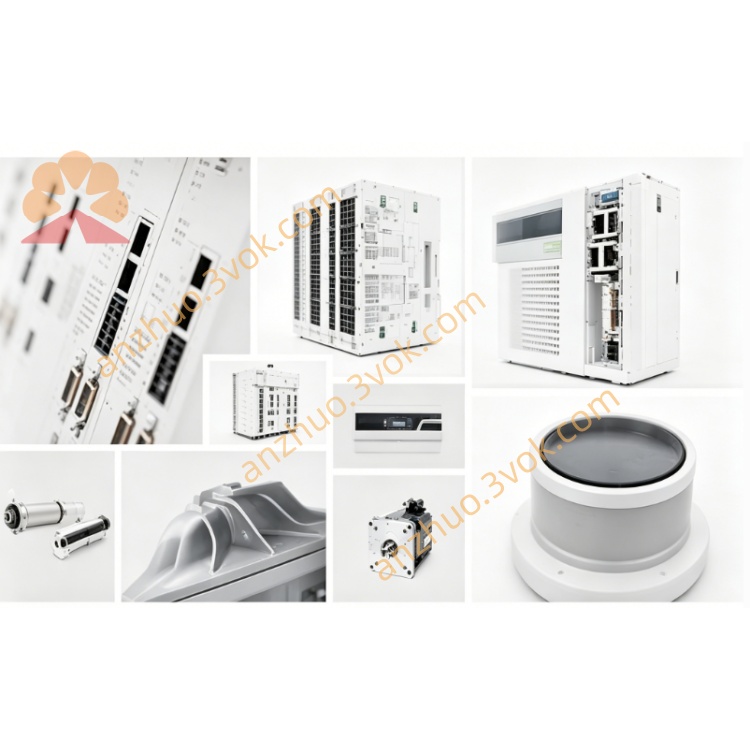
KEBA PS240/A (often written as KEBAPS240) power module I. Product Overview
The KEBA PS240/A is a 24V DC system power module specifically designed for the KeControl/Kemro K2 series of the Austrian KEBA brand. It is part of the KeConnect I/O complementary power supply unit and is tailored for medium-sized industrial control systems such as injection molding, die-casting, and machine tools. The module is installed using a backplane slot system and is directly embedded into the KEBA controller frame. It provides a stable and isolated 24V DC power supply for the CPU, I/O modules, bus interfaces, and peripheral sensors, serving as the core power supply for the entire control system.
II. Core Functions
Wide-range AC input, universal worldwide
Supports 100–240V AC, 50/60Hz, full voltage range automatic adaptation, compatible with global industrial power grids, no manual adjustment required, suitable for deploying devices in different countries.
Stable 24V DC isolated output
Outputs a 24V DC regulated power supply, providing power to the controller, I/O modules, HMI, sensors, and actuators. The input/output is fully electrically isolated, blocking grid interference, and protecting the control loop safety.
Medium-power continuous power supply
Rated output 24V DC / 5A, maximum power 120W, capable of meeting the power supply requirements of small and medium-sized KEBA systems (including CPU + 10–16 I/O modules).
Complete protection mechanism
Integrated overvoltage, overload, short circuit, overheating, reverse polarity protection; automatically shuts off the output and locks it during faults, automatically recovers after fault removal, avoiding system damage and reducing downtime risks.
Industrial-grade efficient energy saving
Uses high-frequency switching power supply technology, efficiency ≥ 90%, low energy consumption, low heat generation; natural convection cooling (no fan), avoiding dust accumulation, improving long-term operational reliability.
LED status diagnosis
Equipped with a normal power LED (green) and a fault LED (red): Green constantly on indicates normal output; Red lighting indicates overvoltage / overload / short circuit / overheating, quickly locating power supply faults.
Backplane bus integration, plug-and-play
Connects to the controller through KEBA's dedicated K-bus backplane bus, automatically identified, no configuration required; supports hot swapping, can directly replace modules during operation, no need to stop and power off.
Adaptation to harsh industrial environments
Strengthened PCB, industrial-grade components, fully sealed dust-proof design, anti-vibration / shock resistance; wide temperature range suitable for workshop high-temperature, high-humidity, and high-dust scenarios, supports 24-hour continuous operation.
III. Technical Specifications (Official Standard Specifications)
Model: PS240/A (abbreviated as PS240, often written as KEBAPS240)
所属 series: KeControl / Kemro K2 platform (KeConnect I/O companion)
Input voltage: 100–240V AC, 50/60Hz (wide voltage automatic adaptation)
Output voltage: 24V DC (regulated, accuracy ±1%)
Rated output current: 5A (continuous)
Maximum output power: 120W
Isolation method: Input / output electrical isolation (enhanced anti-interference)
Protection functions: Overvoltage, overload, short circuit, overheating, reverse polarity
Efficiency: ≥90%
Cooling method: Natural convection (no fan)
Status indication: Green LED (power normal), Red LED (fault)
Communication interface: KEBA K-bus backplane bus
Installation method: Backplane slot installation of the K2 series controller
Operating temperature: 0℃–+55℃
Storage temperature: –40℃–+70℃
Humidity requirement: 10%–95% (no condensation)
Protection grade: IP20 (module front)
Size (width × height × depth): Approximately 62mm × 160mm × 131mm
Weight: Approximately 1950g
Certifications: CE (EMC/LVD), RoHS, UL 508, EN 61131-2
IV. Design Features
System-specific integrated design
Designed specifically for the KEBA K2 series controller, direct plug-in installation on the backplane, no additional wiring required, simplifies cabinet layout, saves space; perfectly compatible with the K2-200/K2-400 series, new and old systems can be directly replaced. Full-process industrial-level testing (high temperature, low temperature, vibration, shock, EMC), MTBF ≥ 500,000 hours, suitable for 24-hour continuous operation scenarios of injection molding, die-casting, machine tools, etc.
Easy maintenance with low failures
LED intuitive diagnosis, quickly determine power supply status; hot-swappable design supports non-stop replacement, shortens maintenance time; fanless structure avoids dust blockage, reduces failure probability.
Strong isolation and anti-interference
Input/output completely isolated, effectively suppress grid peaks, frequency converter interference, motor start-stop noise, suitable for high electromagnetic interference industrial sites, ensuring system stable operation.
V. Typical Application Scenarios
Injection molding mechanical control system
Power supply for KePlast injection molding machine controller, I/O module, temperature sensor, pressure sensor, electromagnetic valve coil.
Die-casting equipment electrical control system
Drive KeControl die-casting machine CPU, bus module, hydraulic valve control module, safety door detection sensor.
Industrial machine tools / processing centers
Power supply for KeMotion motion controller, servo driver, I/O module, spindle encoder, cooling pump / lubrication pump control loop.
KEBA standard automation workstation
Adapt to standard workstations with KEBA controller + I/O module, such as robot workstation, packaging line, hydraulic control system, etc.
VI. Installation and Wiring Key Points Installation steps
First Installation: Power off the controller, align the K2 series backplane slot and push it in smoothly, then lock it with the clip;
Module Replacement: Supports hot swapping. Simply pull out the old module and insert the new one. The controller will automatically recognize it, and no restart is required.
Wiring Specifications
AC Input: L (hot wire), N (neutral wire), PE (ground wire) connect to a 100–240V AC power grid, with reliable grounding of the ground wire;
DC Output: Positive (+) and negative (-) poles of 24V DC connect to the 24V common bus of the system, providing power to the CPU and I/O modules;
Wire Diameter Selection: 1.0–1.5mm² on the AC side, 1.5–2.5mm² on the DC side. Separate strong and weak current wiring to reduce interference.
VIII. Troubleshooting Guide
Green LED does not light up, no output
Check if the AC input voltage is normal and if the wiring is loose;
Confirm if the module is inserted properly and the K-bus bus connection is normal;
Check if it is due to overheating protection shutdown, and restart after power off for cooling.
Red LED lights up, abnormal output
Immediately cut off the power supply, check if there is a short circuit on the DC output side or if the load is damaged;
Check if the load current exceeds 5A and the total power exceeds 120W;
Confirm if the environmental temperature is too high or if the ventilation is poor.
Unstable output voltage, large fluctuations
Check if the AC input voltage fluctuates too much;
Check if there are large power inductive loads on the DC output side that frequently start and stop;
Confirm if the system grounding is good, and if the controller and power module are grounded together.
Get a Quote