
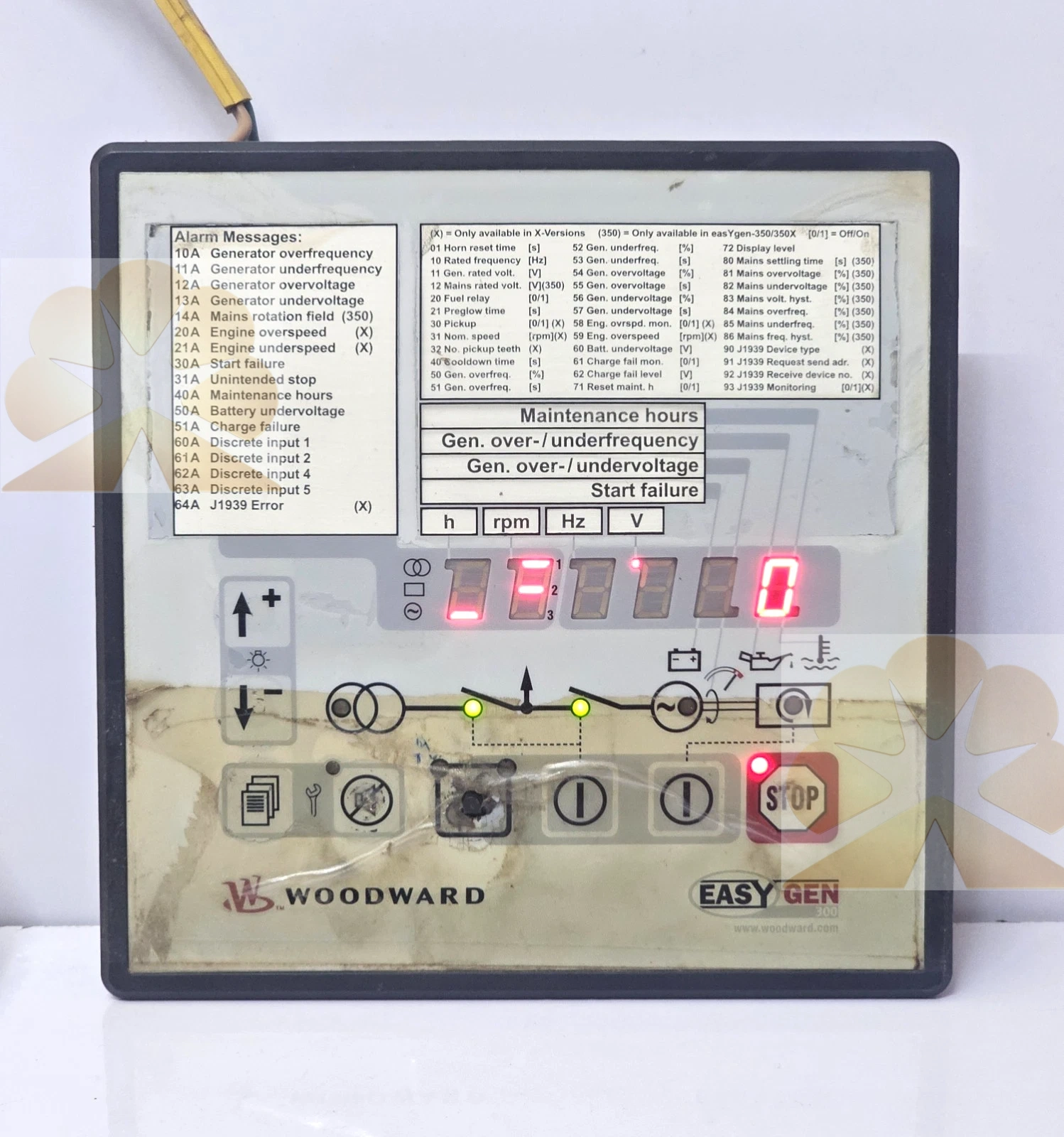
WOODWARD 8440-1801 REV:C 16665352 0909: easYgen-350/X Genset Controller Product Description
Description
WOODWARD 8440-1801 REV:C 16665352 0909: easYgen-350/X Genset Controller Product Description
Brand and Product Identification
The WOODWARD 8440-1801 REV:C, with internal manufacturing and traceability reference 16665352 0909, is an easYgen-350/X series genset controller built for single-unit isolated generator set operation. The 8440-1801 is the official Woodward part number, REV:C denotes hardware revision C of the control unit, and the easYgen-350/X product identifier corresponds to this compact engine-generator control platform. Optimized for diesel engine generator sets, the controller integrates automatic start/stop sequencing, electrical metering, generator protection and mains failure auto-start functions into a single panel-mount device.
Product Function and System Role
The easYgen-350/X manages the full operating cycle of standby or prime power generator sets: it automatically starts the engine when mains power fails, monitors generator and engine parameters, triggers protective actions under fault conditions, and returns the load to utility supply then stops the engine once grid power is restored. It handles pre-glow control, start sequence logic, runtime counting and alarm classification, acting as the core control unit for small to medium generator packages. It is a dedicated genset controller, not a standalone engine governor, alternator, circuit breaker, automatic transfer switch or fuel system actuator by itself.
Electrical and Measurement Specifications
Operating supply voltage ranges from 6.5 V DC to 32.0 V DC, compatible with standard 12 V and 24 V DC generator battery systems. The controller performs true RMS measurement of generator voltage, with a maximum measurable level up to 346/600 V AC. It tracks generator frequency across 40–85 Hz, engine rotational speed, and derived operational parameters from connected engine sensors. Insulation withstand voltage is rated at 1500 V DC between measurement circuits and control logic, and measurement accuracy meets industrial genset control requirements for protection and monitoring functions.
Control and Protection Functions
The controller executes a complete automatic start/stop sequence for diesel engines, including pre-glow control for cold starting, crank attempt limits and idle run timing. It provides comprehensive generator and engine protection with configurable trip levels, time delays and alarm classes: overvoltage, undervoltage, overfrequency, underfrequency and engine-related fault conditions each trigger defined responses from warning notification to immediate shutdown. Built-in AMF automatic mains failure logic enables unattended standby generator operation and reliable load transfer during utility outages.
Display and Operator Interface
The front panel features a 6-digit 7-segment LED display capable of showing measured values (voltage, frequency, engine speed), runtime counters, alarm messages and engine ECU data. Navigation and operation buttons support local parameter viewing and configuration, with front-panel parameter access protected by password to prevent unauthorized setting changes. A 15-entry event logger records fault and operational events for maintenance and troubleshooting. Custom paper-strip labels can be applied to define frequently used display items for quick on-site reference.
Communication and Configuration
A CAN bus interface supports connection to SAE J1939 compliant engine ECUs, allowing the controller to read engine operating data, fault codes and sensor values directly from the engine management system. Configuration can be performed either via the front panel buttons or through a PC-based configuration tool for full parameter setup and firmware updates. The CAN bus architecture simplifies integration with modern electronically controlled diesel engines and reduces external wiring for engine sensor signals.
Mechanical Construction and Environmental Ratings
The controller uses a compact panel-mount housing with overall dimensions of 158 mm width, 158 mm height and 40 mm depth, weighing less than 450 grams. Degree of protection is IP20 on the terminal side, intended for installation inside generator control panels or enclosed cabinets. Endurance vibration rating is 4 G at 30 Hz for 1.5 hours, and temperature performance conforms to IEC 60068-2-1 / 2 / 30 standards for industrial environmental conditions. The front bezel fits a standard panel cutout for flush mounting on generator control doors.
Typical Application Scenarios
Typical applications include standby diesel generator sets for commercial buildings, data centers, telecom base stations, small industrial facilities, construction site generators, irrigation pump units and rural off-grid power systems. The controller is also widely deployed in rental generator fleets, emergency backup power packages and small prime power installations where automatic mains failure response and basic engine protection are required.
Installation and Commissioning Notes
Installation shall follow the Woodward easYgen-350/X user manual, generator wiring diagrams and local electrical codes. Mount the controller into the prepared panel cutout, connect the battery supply, generator voltage sensing leads, engine sensor signals, start relay, fuel solenoid and alarm output circuits according to the terminal diagram. Configure nominal voltage, frequency, engine start parameters, protection thresholds and alarm classes via the front panel or PC software. Verify crank sequence, pre-glow timing, voltage and frequency readings, protection trip behavior and auto start/stop transfer logic before placing the generator set into service.
Advantages and Selection Notes
The 8440-1801 easYgen-350/X offers integrated single-unit genset control with AMF functionality, true RMS electrical measurement, comprehensive generator and engine protection, J1939 CAN engine interface, 6-digit LED display, 15-entry event logger, password-protected configuration, wide 6.5–32 V DC supply range and compact panel-mount construction. When selecting a replacement, confirm the easYgen-350/X model, hardware revision, supply voltage range, CAN bus requirement and suitability for single-unit isolated operation. The device is a genset controller, not a parallel load-sharing unit, governor actuator, alternator AVR or transfer switch; its role is to supervise and control the operating sequence, measurement and protection of a single generator set.
Get a Quote