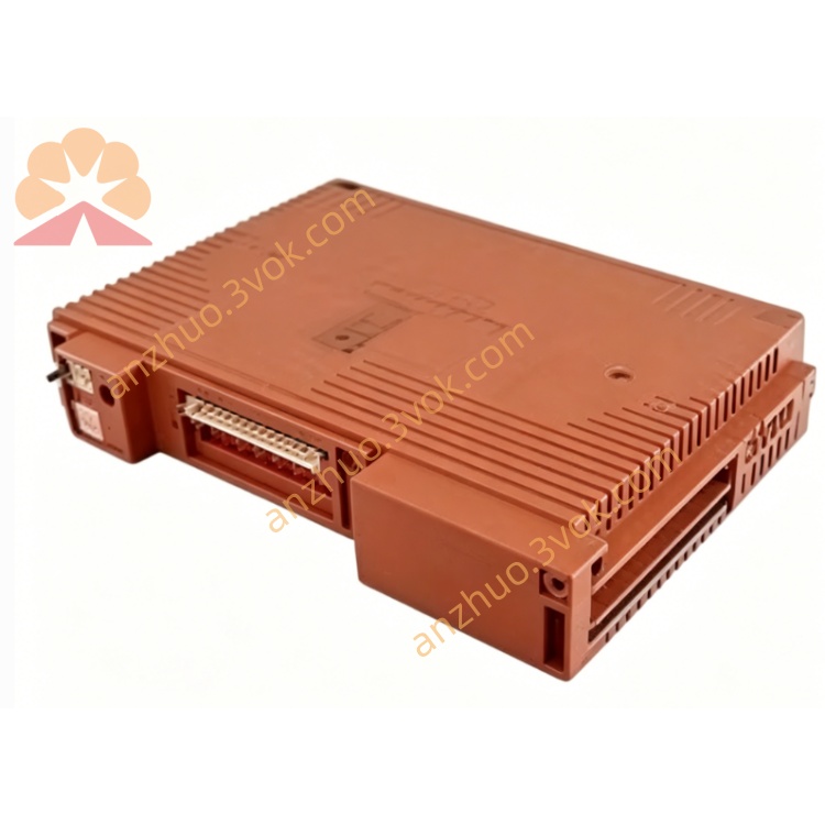
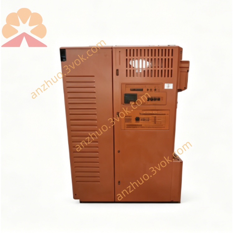
Yokogawa SCP461-11S1 CENTUM VP DCS Main Processor Module
Description
2. Key Features
Model: SCP461-11S1 (standard temperature version)
Architecture: 32‑bit RISC CPU, dual-core safety design
Safety: IEC 61508 SIL 3, IEC 61511 compliant
Memory: 256 MB SDRAM / 64 MB Flash
Processing Speed: Up to 50 kHz safety loop
Redundancy: 1:1 hot‑swap redundant support
Communication: Dual Ethernet (10/100 Mbps), RS‑232C, RS‑485
I/O Capacity: Supports up to 1024 safety I/O points
Power: 24 V DC ±10%, 12 W typical
Operating Temp: –20 °C to +40 °C (S1 version)
3. Safety Precautions
Disconnect 24 V DC power before installation, wiring, or maintenance.
Install in a 19‑inch EIA rack with adequate ventilation (≥50 mm clearance).
Separate safety signal cables from non‑safety cables to avoid interference.
Only qualified safety automation personnel may configure, program, or replace the module.
Do not open or modify the module; no user‑serviceable parts inside.
For SIL 3 applications, maintain redundant CPU configuration and periodic proof tests.
4. Installation
4.1 Rack Mounting
Insert SCP461-11S1 into a standard 19‑inch rack slot (3U height).
Align module rails, push fully into the backplane, and tighten front panel screws.
For redundancy, install a second SCP461-11S1 in the adjacent slot.
Ensure sufficient airflow; avoid blocking ventilation holes.
4.2 Terminal Wiring
PWR1/PWR2: 24 V DC (dual power input for redundancy)
ETH1/ETH2: Ethernet ports for system communication
RS‑232C: Local configuration port (engineering tool)
RS‑485: Fieldbus communication (Modbus RTU)
RED: Redundancy link (connect between primary and secondary CPU)
5. Front Panel Indicators
PWR (Green): ON = power normal; OFF = no power
RUN (Green): ON = CPU in run mode; Blinking = self‑test/boot
ERR (Red): ON = safety fault; Blinking = minor alarm
RX/TX (Yellow): Flashing = Ethernet/serial activity
RDY (Green): ON = redundant mode ready (secondary CPU)
6. Basic Operation
Power‑On & Self‑Test
Apply 24 V DC power to PWR1/PWR2.
Module performs self‑test (~45 seconds): RUN blinks, ERR off.
After successful test: RUN steady green; system enters safety run mode.
Redundancy Operation (Dual CPU)
Install two SCP461-11S1 modules and connect the RED redundancy cable.
Power on both CPUs; primary CPU executes safety logic, secondary synchronizes data.
If primary fails, secondary takes over automatically (hot‑swap) with no process interruption.
Configuration
Connect PC to RS‑232C or ETH1 port.
Use Yokogawa ProSafe‑RS Engineering Software.
Set IP address, redundancy mode, safety logic, and I/O parameters.
Download configuration to CPU; save to non‑volatile memory.
7. Main Parameters
CPU Loop Time: 20–1000 µs (configurable)
Redundancy: Enable/Disable (default: Enable if dual CPU)
Default IP: 192.168.1.20 (ETH1), 192.168.2.20 (ETH2)
Subnet Mask: 255.255.255.0
Gateway: 0.0.0.0 (default)
RS‑485 Baud Rate: 9600 bps (default)
8. Fault & Error Codes
E01: Power supply fault (check 24 V DC wiring)
E02: Safety logic mismatch (re‑download valid config)
E03: Redundancy link loss (check RED cable)
E04: Communication fault (Ethernet/RS‑485 cable)
E05: I/O module fault (check I/O backplane/modules)
E06: CPU overheating (check ventilation/ambient temp)
9. Specifications
Model: SCP461-11S1
Safety Rating: IEC 61508 SIL 3, IEC 61511
CPU: 32‑bit RISC, dual-core safety
Memory: 256 MB SDRAM, 64 MB Flash
Power: 24 V DC ±10%, 12 W
Operating Temp: –20 °C to +40 °C
Humidity: 10–90% RH (non‑condensing)
Dimensions: 130 × 482 × 305 mm (3U, 19‑inch rack)
Weight: Approx. 5.0 kg
Certifications: CE, ATEX, IECEx
10. Maintenance
Keep rack and module clean; avoid dust, moisture, and corrosive gases.
Check power cables and redundancy cables monthly for tightness.
Verify Ethernet/RS‑485 connections quarterly.
Back up safety configuration every 6 months.
Perform proof test annually for SIL 3 applications (per IEC 61511).
Get a Quote