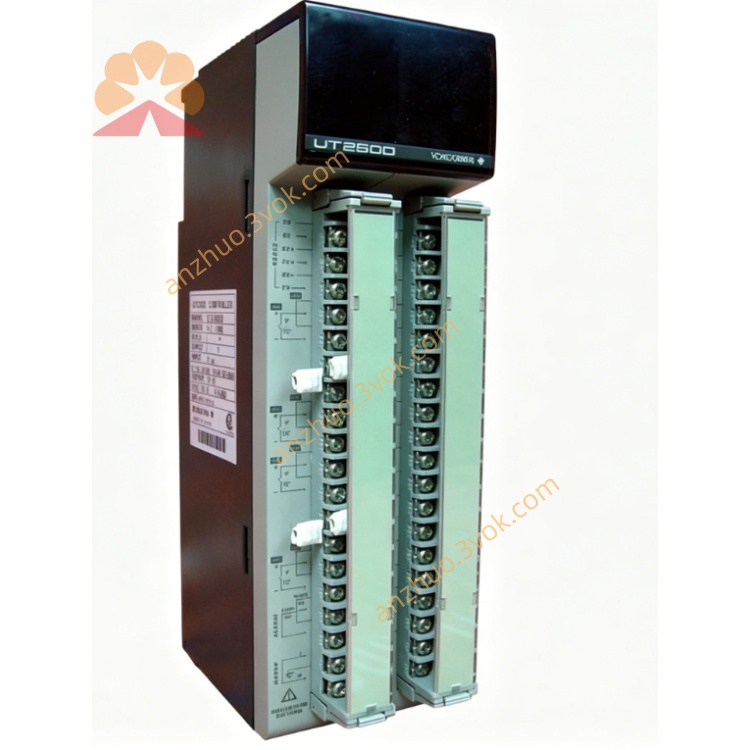
Yokogawa UT2800-1/HB High-Performance Digital Indicating Process Controller
Description
General Information
2. Features
Model: UT2800-1/HB
Built-in HB High Alarm: Dedicated high-limit alarm relay output
Universal Input: Thermocouple (K, J, E, T, N, R, S, B); RTD (Pt100); DC 4–20 mA, 0–10 V
Dual LED Display: PV (process value) / SP (setpoint)
Control Modes: ON/OFF, PID with auto-tuning
Alarm Output: 1 relay (250 VAC, 3 A resistive) for HB high alarm
Power Supply: 100–240 VAC, 50/60 Hz
Dimensions: 96 × 96 × 100 mm (1/4 DIN)
Accuracy: ±0.1% of full scale
3. Safety Precautions
Disconnect power before wiring or maintenance.
Separate signal and power cables to avoid electrical interference.
Avoid installation in locations with vibration, corrosive gas, direct sunlight, or condensation.
Only qualified personnel may perform wiring and parameter setup.
Do not disassemble the unit; no user-serviceable parts inside.
4. Installation
4.1 Panel Mounting
Cut a 92 × 92 mm square hole in the panel (thickness 1–5 mm).
Insert the controller from the front.
Secure with rear mounting brackets and tighten screws.
Ensure the front panel is flush.
4.2 Terminal Wiring
1–2: Power (100–240 VAC)
3–4: HB Alarm relay (NO/COM)
5: Not used (reserved)
6–7: Sensor input (+/–)
8: Common ground (GND)
5. Front Panel Operation
5.1 Panel Keys & Indicators
PV Display (Upper): Process value (temperature/process variable)
SP Display (Lower): Setpoint or parameter value
HB Indicator: Lights when high alarm is active
SET Key: Enter/confirm parameters
▲/▼ Keys: Adjust values, select parameters
◄ Key: Move cursor left
5.2 Basic Operation
Power-On
Setpoint Adjustment
Press SET briefly (SP display flashes).
Use ▲/▼ to modify the setpoint.
Press SET or ENT to save.
Parameter Entry
Hold SET for 3 seconds to enter setup mode.
Use ▲/▼ to select a parameter.
Press SET to edit.
Adjust value with ▲/▼ and ◄.
Press SET to save.
Hold SET 3 seconds to exit.
6. HB High Alarm Parameters
HB.L: High alarm limit (PV ≥ HB.L → alarm ON)
HB.HY: Alarm hysteresis (prevents rapid on/off cycling)
HB.MD: Alarm mode (normally open / normally closed)
When PV exceeds HB.L, the relay activates and the HB lamp lights.
7. Input Type Selection
K/J/E/T/N/R/S/B: Thermocouple
Pt100: RTD
4–20mA / 0–10V: Analog input
8. Error Codes
Err 01: Sensor open circuit
Err 02: Input overrange
Err 03: Input underrange
Err 04: Internal hardware fault
Err 05: HB alarm circuit error
9. Specifications
Input: Universal (TC/RTD/DC)
Control: ON/OFF, PID auto-tuning
Alarm: 1×HB high-limit relay
Accuracy: ±0.1% FS
Power: 100–240 VAC, 50/60 Hz
Display: Dual 4-digit LED
Operating Temp: 0–50°C
Humidity: 10–90% RH (non-condensing)
Weight: Approx. 0.5 kg
10. Maintenance
Clean the front panel with a soft, dry cloth.
Do not use solvents or water.
Check terminal connections periodically for tightness.
Calibrate annually for precision applications.
Get a Quote