Yokogawa SCP451-11CPU ProSafe-RS Safety Control Processor Module
Description
2. Key Features
Model: SCP451-11CPU (S1 suffix: standard)
Core: 32‑bit RISC CPU @ 400 MHz
Memory: 128 MB SDRAM / 16 MB Flash
Processing Speed: 30 kHz loop execution
Redundancy: Dual redundant support (hot‑swap)
Communication: Ethernet 10/100 Mbps, RS‑232C, RS‑485
Safety: IEC 61508 SIL 3 certified, fault‑tolerant design
Input/Output: 16 analog in, 8 discrete in, 8 discrete out (base)
Power: 24 V DC ±10%, 10 W typical
Environ‑
ment: –25 °C to 70 °C (F version); –20 °C to 40 °C (S version)
3. Safety Precautions
Disconnect 24 V DC power before installation/wiring/maintenance.
Install in a 19‑inch rack with keyed metal cabinet (safety/EMC compliance).
Separate signal cables (Ethernet/RS‑485) from power cables to avoid interference.
Only qualified safety/automation personnel may configure, program, or replace the module.
Do not open or modify the module; no user‑serviceable parts inside.
For safety‑critical applications, maintain redundant CPU configuration and regular testing.
4. Installation
4.1 Rack Mounting
Insert the SCP451-11CPU into a standard 19‑inch rack slot (height: 3U).
Align the module rails, push fully home, and tighten front panel screws.
Ensure adequate ventilation (≥50 mm clearance top/bottom).
For redundancy, install a second SCP451-11CPU in the adjacent slot.
4.2 Terminal Wiring
PWR: 24 V DC ±10% (positive/ground)
ETH1/ETH2: Ethernet (10/100 Mbps) for system communication
RS‑232C: Serial port for local configuration
RS‑485: Fieldbus/device communication
I/O: Analog/digital I/O terminals (per system wiring diagram)
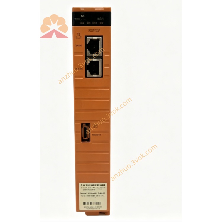
5. Front Panel Indicators
PWR: Green = power ON; OFF = no power
RUN: Green = CPU running normally; Blinking = self‑test/boot
ERR: Red = fault (CPU, I/O, communication)
RX/TX: Yellow = Ethernet/serial data activity
RED: Green = redundant mode active; OFF = single CPU
6. Basic Operation
Power‑On & Self‑Test
Apply 24 V DC power.
The module runs self‑test (RUN blinks, ERR off).
After ~30 seconds, RUN steady green; system enters run mode.
Redundancy Setup (Dual CPU)
Install two SCP451-11CPU modules in adjacent slots.
Connect redundancy cable between the two CPUs.
Power on both modules; primary CPU controls, secondary syncs data.
If primary fails, secondary takes over automatically (hot‑swap).
Configuration (via RS‑232C/Ethernet)
Connect PC to RS‑232C or Ethernet port.
Use Yokogawa ProSafe‑RS engineering software.
Set IP address, redundancy mode, I/O parameters, and control logic.
Download configuration to CPU; save to non‑volatile memory.
7. Main Parameters
CPU Speed: 400 MHz (fixed)
Loop Time: 10–30,000 µs (configurable)
Redundancy: Enable/Disable (default: Enable if dual CPU)
IP Address: 192.168.1.10 (default)
Subnet Mask: 255.255.255.0 (default)
Gateway: 0.0.0.0 (default)
Baud Rate (RS‑485): 9600 bps (default)
8. Fault & Error Codes
E01: Power supply fault (check 24 V DC)
E02: CPU overheating (check ventilation)
E03: Communication loss (Ethernet/RS‑485 cable)
E04: I/O module fault (check I/O wiring/modules)
E05: Redundancy mismatch (check redundant CPU/cable)
E06: Configuration error (re‑download valid config)
9. Specifications
Model: SCP451-11CPU (S1)
CPU: 32‑bit RISC @ 400 MHz
Memory: 128 MB SDRAM, 16 MB Flash
Power: 24 V DC ±10%, 10 W
Operating Temp: –25 °C to 70 °C (F); –20 °C to 40 °C (S)
Humidity: 10–90% RH (non‑condensing)
Dimensions: 130 × 482 × 305 mm (3U, 19‑inch rack)
Weight: Approx. 4.5 kg
Certification: IEC 61508 SIL 3, CE, ATEX
10. Maintenance
Keep the rack clean and dry; avoid dust/corrosive gas.
Check power cables and redundancy cables monthly for tightness.
Verify fan operation (F version) quarterly; replace if noisy.
Back up CPU configuration every 6 months.
Calibrate I/O channels annually for precision applications.
Get a Quote