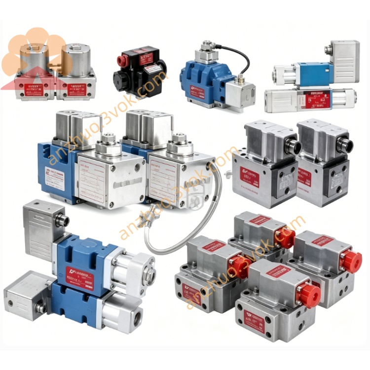
MOOG D663-1922E-4 Servo Valve
Description
Model Code Definition
D663 = Base series: ISO4401-05 NG10 mounting dimension, ServoJet jet-pipe pilot, embedded integrated amplifier + full-range LVDT spool feedback
1922 = Factory unique trim code, defines fixed rated flow, pre-calibrated null bias, locked amplifier gain and matched internal pilot assembly
E = Enhanced thermal drift compensation circuit, standard FKM fluororubber sealing for industrial medium temperature range
-4 = Custom option code: modified partial underlap spool + thicker valve body casting, optimized mounting flange for anti-shock & high vibration operating site
Technical Specifications
Hydraulic Parameters
Rated Flow:175 L/min @35bar single-land differential pressure; peak instantaneous flow 292 L/min @70bar supply differential pressure
Max Working Pressure:P/A/B main ports up to 350bar; internal T drain ≤50bar; standalone Y external drain withstand full 350bar rated pressureMoog Inc.
Full Stroke Step Response:≤22.2ms under standard 210bar supply pressure
Control Precision:Hysteresis<0.17%FS, Resolution<0.069%FS, overall thermal drift(-20~+60℃)<2.02%FS
Null Leakage:0.45~2.88 L/min
Working Medium:Anti-wear mineral hydraulic oil, cleanliness NAS6~7 / ISO4406 17/14/11, fluid operating temperature -20℃~+80℃
Net Weight:3.05kg (extra 0.16kg vs standard E version due to "-4" reinforced body)
Electrical Parameters
Input Power:24VDC wide input(18~32VDC), static standby current ≤630mA
Standard Control Command:±10VDC differential analog input; ±10mA /4~20mA current signal available via factory custom order
EMC Standard:Comply with EN55011 industrial EMC; 7-pin military circular connector, IP65 after complete cable wiring
Port & Connection Configuration
Hydraulic Interface:Standard ISO4401-05 NG10 mounting hole layout, separated P supply, A/B actuator control ports, built-in T internal drain + independent Y external drain; "-4" version with reinforced mounting bolt boss on valve bottom
Electrical Interface:7-pin circular receptacle integrating power, analog command and full-travel LVDT feedback; double-shielded control cable with single-point cabinet grounding
Control Mode:Pure analog closed-loop regulation, no digital fieldbus interface
Core Functions
1.Patented ServoJet jet-pipe pilot delivers superior anti-contamination compared with nozzle-flapper structure, stable operation under moderately contaminated hydraulic fluidMoog Inc.。
2.E-type enhanced amplifier cooperates with full-range LVDT closed loop to automatically compensate temperature-induced null drift; "-4" reinforced structure improves anti-fatigue performance under continuous mechanical vibration。
3.Spring-centered fail-safe spool:automatically returns to neutral on power loss to block A/B oil passage and lock hydraulic actuator for equipment safety protection。
4.Partial modified underlap spool of "-4" option reduces startup impact flow, effectively suppress hydraulic shock during frequent reversing control。
Typical Application
Large-tonnage hydraulic forging press, heavy-duty steel slab rolling mill tension control, automobile hot stamping production line, high-load material fatigue test bench, large composite thermal forming hydraulic equipment, mine hydraulic servo driving unit.
Installation & Maintenance Instructions
1.Install 3μm high-pressure precision inline filter on upstream supply pipeline; replace initial filter cartridge after 15 working days of commissioning startup。
2.Arrange power and shielded control wire inside independent wiring duct to avoid inverter harmonic interference on analog control signal; fix valve mounting bolts with spring lock washer for "-4" anti-vibration installation requirement。
3.Null bias and flow gain fully pre-calibrated at MOOG factory; only minor on-site potentiometer fine adjustment permitted; complete disassembly of ServoJet pilot and main spool assembly is strictly forbidden。
4.Seal all unused hydraulic ports with dedicated blank plugs during spare storage; store inside dry dustproof warehouse to prevent FKM seal ageing and oil leakage。
Get a Quote