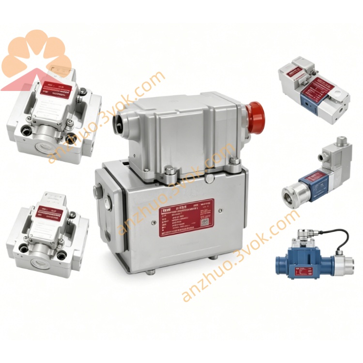
MOOG D663-1914E Servo Valve
Description
Model Code Definition
D663 = Base model: ISO4401-05 NG10 mounting dimension, ServoJet jet-pipe pilot stage, onboard integrated amplifier + full-range LVDT spool position feedback
1914 = Factory exclusive trim code, defines fixed rated flow value, preset null offset, locked amplifier gain and matched internal pilot assembly specification
E = Enhanced PCB circuit version with improved thermal drift compensation, standard FKM fluorocarbon rubber sealing for general industrial environment
Technical Specifications
Hydraulic Parameters
Rated Flow:142 L/min @35bar single-side differential pressure; peak instantaneous flow 238 L/min @70bar supply differential pressure
Max Working Pressure:P/A/B main control ports 350bar; internal T drain ≤50bar; standalone Y external drain tolerates full 350bar pressure
Full Stroke Step Response:≤21.8ms under standard 210bar supply oil pressure
Control Precision:Hysteresis<0.16%FS, Resolution<0.068%FS, total thermal drift(-20~+60℃)<1.98%FS
Null Leakage:0.38~2.62 L/min
Working Medium:Anti-wear mineral hydraulic oil, fluid cleanliness NAS6~7 / ISO4406 17/14/11, operating fluid temperature -20℃~+80℃
Net Weight:2.89kg
Electrical Parameters
Input Power Supply:24VDC wide range input(18~32VDC), static standby current ≤610mA
Standard Command Signal:±10VDC differential analog input; ±10mA /4~20mA current signal available via factory customized order
EMC Standard:Comply with EN55011 industrial electromagnetic compatibility standard; 7-pin military circular connector, IP65 protection after complete cable installation
Port & Connection Configuration
Hydraulic Interface:Standard ISO4401-05 NG10 base mounting hole layout, separated P supply port, A/B actuator control ports, built-in T internal drain and independent Y external drain port
Electrical Interface:7-pin circular receptacle integrating power supply, analog command and full-stroke LVDT feedback wiring; double-shielded control cable with single-point grounding inside control cabinet
Control Mode:Pure analog closed-loop regulation, no digital fieldbus communication interface
Core Functions
1.Patented ServoJet jet-pipe pilot has superior anti-contamination property versus conventional nozzle-flapper design, securing stable long-running operation under moderately polluted hydraulic oil environment.
2.E-type enhanced built-in amplifier cooperates with full-range LVDT closed loop to automatically compensate temperature-caused null drift, better environmental adaptability than ordinary standard circuit version.
3.Spring-centered fail-safe spool structure:main spool returns to neutral position automatically upon power failure to block A/B oil passage and lock hydraulic actuator for equipment safety protection.
4.Optimized internal flow passage keeps excellent linear flow gain, supports flexible switching among position, velocity and pressure three closed-loop control modes.
Typical Application
Medium-tonnage hydraulic forging press, automotive part precision stamping line, small-medium steel strip mill tension control system, hydraulic component fatigue test bench, medium-size composite hot-press forming machine, high-precision injection molding clamping hydraulic unit.
Installation & Maintenance Instructions
1.Mount 3μm high-pressure precision inline filter on upstream supply pipeline; replace initial filter cartridge after 15 working days of equipment commissioning startup.
2.Arrange power cable and shielded control wire in independent wiring troughs to avoid frequency converter harmonic interference on analog control command.
3.Null bias and flow gain are fully pre-calibrated at MOOG original factory; only minor on-site potentiometer fine adjustment permitted; full disassembly of ServoJet pilot and main spool assembly is strictly forbidden.
4.Seal all unused hydraulic ports with dedicated blank plugs during spare parts storage; store inside dry dustproof warehouse to prevent FKM seal ageing and hydraulic fluid leakage.
Get a Quote