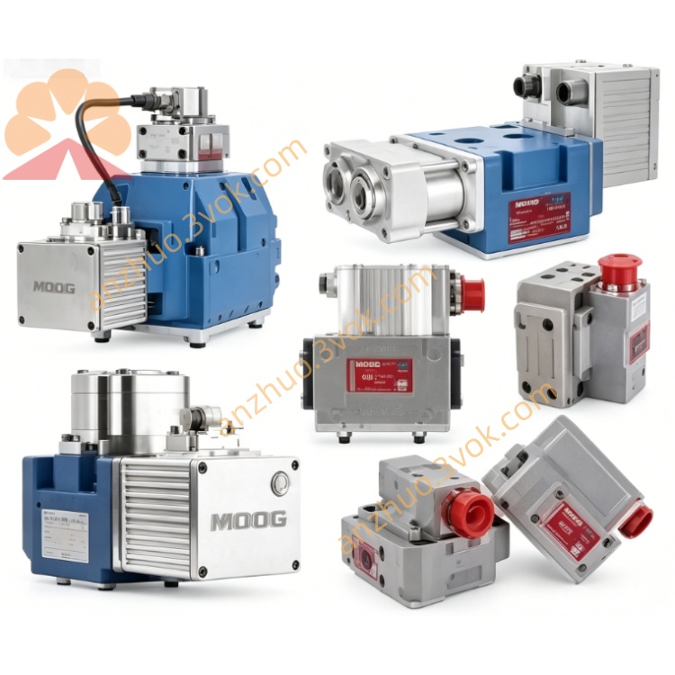
MOOG D662-4118B Servo Valve
Description
Model Interpretation
D662: NG16 standard installation base, ServoJet jet pipe pilot, valve body integrated drive electronic control module series
4118: Flow encoding, unilateral throttling pressure difference 35bar, rated flow 1275L/min, higher than 4115 (1230L/min); internal control T return oil + Y independent external oil outlet configuration; standard suffix D02HYBF5VSD5-O, O-type neutral function, NBR nitrile seal, ±10V differential voltage command, 7-pin aviation plug, full travel LVDT feedback, paired with pilot valve D061-9318
B: Improved valve body, optimized pilot flow path, reduced zero drift at high and low temperatures, reduced internal leakage, enhanced resistance to impurities. Technical Specifications
Hydraulic parameters
Rated flow rate: 1275 L/min (single throttle edge ΔP = 35 bar); Maximum flow capacity at 70 bar pressure difference limit ≈ 2310 L/min
Pressure-bearing: Maximum pressure in the main oil circuit of P/A/B is 350 bar; Internal control T return oil ≤ 50 bar; External leakage Y port withstands pressure of 350 bar
Dynamic response: Under the supply pressure of 210 bar, the 100% full stroke step response is less than 29 ms
Control accuracy: Hysteresis < 0.2% FS, resolution < 0.1% FS, full temperature zero drift < 2.28% FS (the revised version of B is superior to the standard version)
Zero position leakage: 0.75 - 3.70 L/min
Medium: Mineral hydraulic oil, oil cleanliness level NAS6 - 7, working oil temperature -20°C to +80°C
Overall net weight: 3.82 kg
Electrical parameters
Power supply: DC24V (18 - 32VDC wide voltage input), static power consumption of the entire machine ≤ 700mA
Standard control instructions: ±10VDC differential voltage, optional ±10mA, 4 - 20mA current signal
Electromagnetic: EN55011 industrial EMC certification, factory plug protection IP65.
Interface and communication configuration
Hydraulic interface: ISO4401-07 NG16 standard installation holes, P inlet, T internal control return oil, A/B load oil ports, Y independent external leakage oil ports
Electrical interface: 7-pin circular aviation socket, integrated power supply, control signal, LVDT feedback, control line double-layer shielding, single-point grounding of control cabinet
Control mode: Pure analog closed-loop control, no fieldbus communication interface. Core function
1. The ServoJet jet tube has a pre-installed structure. Version B optimizes the internal flow path, tolerates fine impurities in the oil, and has a lower failure rate in harsh metallurgical conditions.
2. The built-in LVDT valve core is fully closed-loop + integrated drive board. It automatically compensates for temperature drift in real time and supports 24-hour continuous full-load operation.
3. The D02 configuration has an O-type neutral position. In the event of power loss, the spring returns to the center to lock the A/B oil chambers, ensuring the hydraulic cylinder maintains pressure and lock, meeting the equipment fault safety standards.
4. The ultra-large flow passage specification ensures excellent flow linearity. A single valve can freely switch position, speed, and pressure for multi-closed-loop control. Applicable scenarios
The AGC press-down system of the thick plate hot rolling unit, the multi-directional forging main machine of 10,000 tons capacity, the ultra-large horizontal die-casting high-speed injection unit, the high-power hydraulic comprehensive test bench, the giant composite material hot pressing forming equipment, and the heavy-load multi-channel fatigue hydraulic testing machine.
Operation and maintenance instructions
1. A 3μm high-pressure precision filter is installed at the front end of the oil inlet pipeline. The first set of filter elements should be replaced 15 working days after the new machine is put into operation.
2. The power cable and the shielded control line are laid in separate channels, isolating the harmonic interference of the frequency converter from the analog control signal.
3. The zero point and gain are calibrated by the original factory. Only minor electrical fine-tuning is allowed on site, and it is strictly prohibited to disassemble the pilot valve and main valve core assembly of the jet pipe.
4. All oil ports are fully sealed for long-term storage. It should be placed in a dry and dust-proof warehouse to delay the aging and leakage of the seals.
Get a Quote