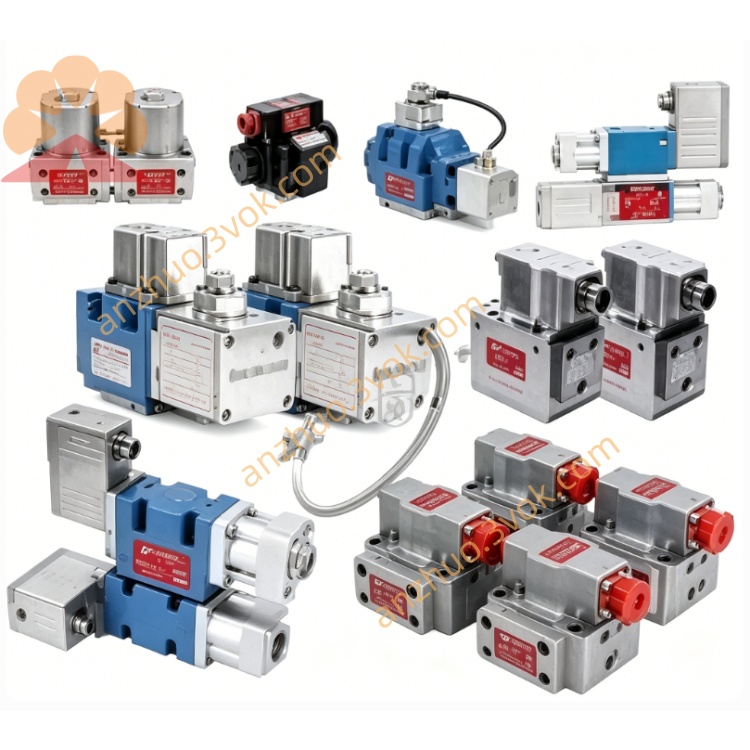
MOOG D662-4011 Servo Proportional Valve
Description
Model Interpretation
D662: NG16 Installation, Secondary Pilot Built-in Electric Control Servo Valve Series
4011: Basic Specification Code, ΔP = 35bar, Rated Flow Rate on One Side = 100L/min, Standard Valve Core Stroke, Internal Return Oil + Independent External Leakage Y-Port Configuration (4010 has 75L/min, 4011 has expanded flow rate)
The suffix can be combined with DxxHABF6VSX2-HA/2-A. The letters define the valve core function, pressure resistance, electrical terminals, control signal, and sealing material (same as 4010 code rule) Technical Specifications
Hydraulic parameters
Rated flow rate: 100 L/min (single throttle edge pressure difference 35 bar)
Maximum pressure: P/A/B = 350 bar; T internal return oil ≤ 50 bar; Y external leakage oil port maximum 350 bar
Step response: 100% full stroke step < 12 ms
Control accuracy: hysteresis < 0.2%, resolution < 0.1%, 55℃ temperature drift < 1.5% FS
Zero position leakage: 0.18 - 1.3 L/min
Applicable media: mineral anti-wear hydraulic oil, oil temperature -20℃ to +80℃, oil cleanliness NAS6 - 7 grade
Overall machine net weight: 2.55 kg
Electrical parameters
Power supply: DC24V (allowable 18 - 32VDC wide input range), total machine power consumption ≤ 320mA
Standard control signal: ±10VDC analog voltage input, supports single-ended / differential wiring
Electrical compliance: EN55011 industrial EMC electromagnetic compatibility standard
Interface and communication configuration
Hydraulic installation: ISO4401-07 standard installation base plate, P inlet, T internal return oil, AB load oil ports, Y external independent return oil port
Electrical connector: 7-pin circular aviation plug, integrated power, command input, valve position feedback terminal, control line must be shielded with single-ended grounding
Control mode: pure analog closed-loop control, no bus communication interface Moog Inc.
Core functions
LVDT valve core built-in closed-loop, valve body circuit board real-time corrects zero point, low and high temperature drift small
ServoJet jet pipe pilot structure, superior ability to resist hydraulic oil impurities compared to nozzle baffle, long-term stability good
Automatic position reset by power-off spring, full position closed pressure retention (D02 function standard O-type position)
4011 large flow specification compatible with cylinder rapid feed, large load speed closed-loop working condition Moog Inc. Applicable scenarios
Medium and large-scale die-locking systems for die-casting machines, hot/cool rolled sheet metal rolling machines, heavy-duty material testing machines, heavy-duty forging hydraulic units, large-scale injection molding high-speed injection closed-loop systems, and engineering machinery hydraulic test benches.
Operation and maintenance instructions
The system's oil inlet and return circuits are equipped with 3μm high-pressure precision filters. The filter elements should be replaced for the first time 15 days after the new machine is put into operation.
The power supply lines and control signal lines are arranged in separate cable trays. Shielded cables are only grounded at one end of the control cabinet.
The factory provides original factory calibration of the zero position. On-site only allows minor electrical fine-tuning. Unauthorized disassembly of the pilot components and valve cores is prohibited.
All oil ports should be sealed for long-term inactivity. Store them dry and dust-free to avoid moisture and rusting of the seals.
Get a Quote