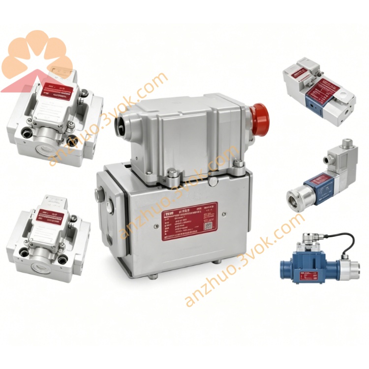
MOOG D662-3303KP01HLMF6NEC2-0 Two-stage ServoJet Pilot Servo Valve
Description
Model Explanation
D662:MOOG D660 series two-stage ServoJet servo valve with ISO4401-07 (NG16) standard installation dimension for medium-large flow
3303:Base specification code: rated flow 240 L/min@ΔP=35bar per single spool land, external independent X pilot oil supply, external Y drain design, zero-lap four-way spool layout
K:ATEX explosion-proof construction with Ex d IIC T6 certification, explosion-proof encapsulated internal drive amplifier
P01:Control signal definition: differential ±10VDC analog input standard configuration
H:Upgraded pressure rating: main P/A/B ports rated for maximum working pressure 315bar
L:Fail-safe feature: mechanical spring auto-centering upon power failure, spool returns to neutral mid-position to lock actuator
M:Built-in non-contact LVDT spool displacement closed-loop feedback inside valve body
F:Standard 6+PE circular aviation electrical connector specification
6:Zero overlap spool, linear flow gain at null position
N:Fluorine high-temperature resistant FKM sealing material upgrade
E:Enhanced EMC reinforced anti-interference circuit design
C2:Customized factory null offset preset and special internal machining tolerance
0:Standard finished product without extra optional auxiliary fittings
Technical Specifications
Hydraulic Parameters
Rated Flow: 240 L/min (@ΔP=35bar per single spool land)
Max Working Pressure: P/A/B main ports:315bar; external Y drain T port:350bar
Pilot Mode: External independent X pilot inlet, external Y drain returning to tank
Working Medium: Mineral hydraulic oil complying with DIN51524/ISO11158, recommended cleanliness NAS6~7
Net Weight: Approx7.7kg
Fail-safe Property: Mechanical return spring automatically centers spool at neutral position when power cuts off
Electrical Parameters
Power Supply: DC24V (18~32VDC), total power consumption ≤44W
Control Signal: Differential ±10VDC analog input
Full Stroke Step Response(0~100% stroke, supply pressure210bar):13~17ms
Electrical Connector: Standard 6+PE circular explosion-proof industrial plug
Built-in Protection: Overcurrent, short-circuit and reverse polarity protection; explosion-proof certified internal circuit
Environmental Conditions
Operating Temperature: -20℃~+75℃; Storage & Transportation:-40℃~+88℃
Humidity:5%~95%RH non-condensing; compliant with EN61000 EMC and ATEX explosion-proof industrial standards
Protection Grade: Connector IP65, valve body IP54 with explosion-proof enclosure
Channel & Feedback Configuration
Hydraulic Port: Standard 4-way P/A/B/T layout following ISO4401-07 manifold dimension, independent external X pilot port and external Y drain port reserved
Feedback Mode: Built-in high-precision non-contact internal LVDT sensor for real-time spool closed-loop feedback without external mechanical feedback rod
Communication & Interface Configuration
Control Wiring: Shielded analog hardwire connection with D137 analog output channel of MSCⅡ control system; control instructions configured via MACS programming software and transmitted by screened signal cables
Auxiliary Interface: Side-mounted zero trimming potentiometer for field on-site zero-offset calibration; only analog hardwire control mode, no onboard EtherCAT or Profibus fieldbus interfaces
Core Function
Convert analog control signals from D136 main controller into large proportional hydraulic flow to drive heavy-load hydraulic cylinders and hydraulic motors for precise closed-loop regulation of position, motion speed and test load.
Internal LVDT collects real-time spool actual position and feeds back to explosion-proof integrated amplifier to form inner closed loop inside valve, improving control linearity and suppressing zero drift induced by oil temperature and supply pressure fluctuation.
Built-in multi-protection amplifier outputs fault alarm signals which can be collected by D137 digital input channels for system interlock protection and fault warning.
Power-off spring centering design ensures actuator locking to avoid runaway risk for explosion-proof industrial equipment safety.
FKM high-temperature sealing and explosion-proof structural design adapt to harsh high-temperature and explosive hazardous working environment; preset factory zero offset reduces field calibration workload.
Applicable Scenarios
Instructions for Installation and Maintenance
Mount on standard ISO4401-07 hydraulic manifold in horizontal or vertical orientation; prohibit installation in uncertified explosive area beyond valve ATEX grade, keep away from dense oil mist and splashing water.
Install 3μm high-pressure precision filters at upstream of P main inlet and X pilot supply port to prevent ServoJet pilot nozzle clogging from hydraulic impurities.
Retighten all explosion-proof electrical terminals every six months; separate shielded analog control cables from high-power power cables inside wiring ducts to reduce electromagnetic interference.
Complete full-range zero calibration once per year; regularly inspect all hydraulic ports for leakage and replace FKM sealing parts when abnormal leakage occurs.
Restrict 24VDC power supply fluctuation within ±10% rated voltage; overvoltage will permanently damage internal explosion-proof amplifier board.
Get a Quote