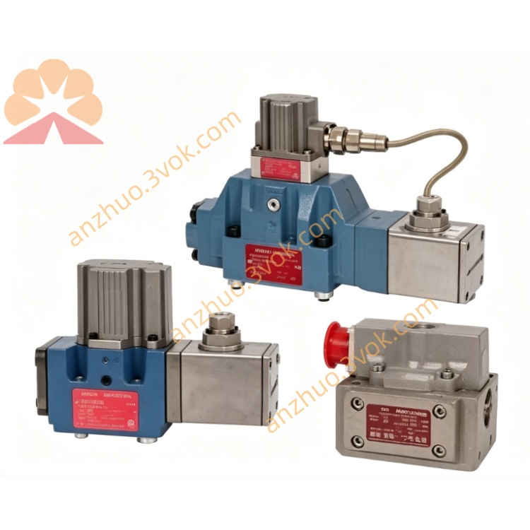
MOOG D661Z2742J Two-stage ServoJet Pilot Servo Valve
Description
Model Explanation
D661:MOOG D660 platform ISO05 Size05 standard two-stage ServoJet servo valve series
Z:Built-in internal LVDT spool closed-loop feedback + fully integrated onboard servo amplifier configuration
2742:Base specification code: rated flow 150L/min@ΔP=35bar per single spool land, external independent X pilot oil supply, external Y drain to tank, power-off mechanical spring auto-centering fail-safe, standard 12-pin circular electrical connector
J:High-pressure upgrade spec: rated design pressure up to 315bar, high-pressure resistant FKM fluorine rubber sealing, reinforced valve body casting and pilot channel anti-high-pressure deformation optimization
Technical Specifications
Hydraulic Parameters
Rated Flow:150 L/min (@ΔP=35bar per single spool land)
Max Working Pressure:P/A/B main ports:350bar(5000PSI); external Y drain T port:350bar(5000PSI); X pilot supply port max 315bar as J customized designMoog Inc.
Pilot Mode:External independent X pilot inlet, external Y drain return to tank
Working Medium:Mineral hydraulic oil conforming to DIN51524/ISO11158, recommended cleanliness NAS6~7
Net Weight:Approx5.9kg
Fail-safe Property:Power-off mechanical spring auto-centering, spool returns neutral automatically to lock actuator position
Electrical Parameters
Power Supply:DC24V(18~32VDC), total power consumption ≤36WMoog Inc.
Control Signal:Differential ±10VDC analog input; optional ±10mA current signal customizationMoog Inc.
Full Stroke Step Response(0~100%, supply pressure210bar):7~10ms
Electrical Connector:12-pin circular industrial plug
Environmental Conditions
Operating Temperature:-25℃~+72℃; Storage & Transportation:-42℃~+88℃
Humidity:5%~95%RH non-condensing; complies with EN61000 industrial EMC anti-interference standard
Protection Grade:Connector IP65, valve body IP54
Channel & Feedback Configuration
Hydraulic Port:Standard 4-way P/A/B/T layout complying with ISO4401-05 manifold mounting dimension, independent external X pilot port and external Y drain reserved
Feedback:Built-in non-contact high-precision LVDT displacement sensor for real-time spool closed-loop feedback, no external mechanical feedback rod
Auxiliary Port:Separate external X pilot oil supply port and external Y drain port defined by model coding
Communication & Interface Configuration
Control Wiring:Shielded analog hardwire connection with D137 analog output channel of MSCⅡ control system; control instructions programmed via MACS software and transmitted by screened control cable
Auxiliary Interface:Side-mounted zero trimming potentiometer for field zero-offset calibration; only analog hardwire control, no onboard fieldbus interface(EtherCAT/Profibus)
Core Function
Convert analog control signal from main controller into proportional hydraulic flow to drive hydraulic cylinder/motor for high-precision closed-loop regulation of position, speed and test load; J high-pressure structure adapts to long-term 315bar system pressure heavy-load working condition.
Internal LVDT collects real spool position and feeds back to integrated amplifier to form valve inner closed loop, improves control linearity and restrains zero drift induced by oil temperature and pressure fluctuation.
Onboard amplifier equipped with overcurrent, short-circuit and reverse polarity protection; valve fault signal can be collected by D137 DI channel for system interlock and fault alarming.
Mechanical spring fail-safe structure prevents equipment runaway when power cuts off, improves safety for high-pressure test equipment.
J-type high-pressure fluorine rubber seal effectively avoids high-pressure oil leakage under long-term ultra-high pressure; optimized pilot runner prevents channel deformation under high system pressure, prolongs service life.
Applicable Scenarios
Heavy-load high-pressure fatigue test of engineering machinery chassis components; ultra-high pressure precision forming control of large hydraulic press; high-pressure electro-hydraulic regulation of steam turbine EH speed governing system; aerospace high-pressure hydraulic actuator performance test bench; new energy material high-pressure compression testing equipment.
Installation and Maintenance Instruction
Install on standard ISO4401-05 hydraulic manifold, horizontal/vertical installation permitted; avoid installation in environment with oil mist, splashing water and intense high-temperature radiation.
Install 3μm high-pressure precision filter on P main oil inlet and X pilot supply port to prevent ServoJet pilot nozzle clogging by hydraulic impurities.
Inspect and retighten electrical terminals every half year, separate shielded signal cable and high-power power cable in wiring duct to reduce EMI interference.
Complete servo valve full-range zero calibration once per year; regularly inspect external leakage of all ports, replace J-spec high-pressure fluorine rubber sealing parts when leakage occurs.
Keep 24VDC power fluctuation within ±10% rated voltage; overvoltage will permanently damage internal integrated amplifier board.
Get a Quote