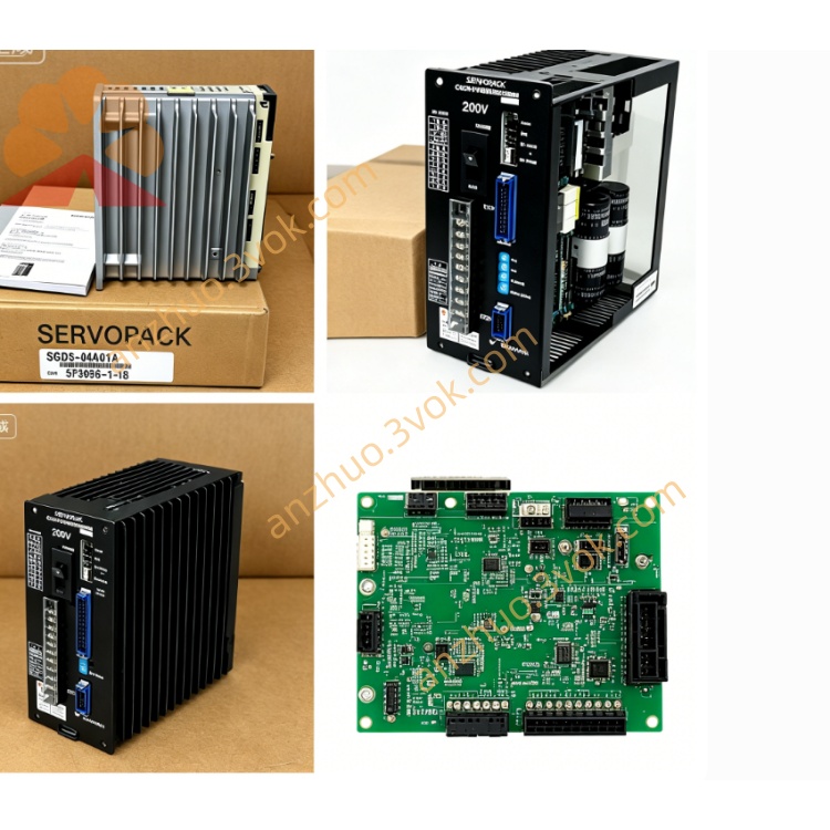
CACR-SR05SB1BF
CACR refers to Yaskawa classic Yasnac VS800 full digital AC SERVOPACK servo amplifier series. SR stands for universal three-control-mode servo drive which supports position, speed and torque control switched by internal parameter setting. 05 means the rated matching motor power is 0.5kW specification. S represents S-version main control board designed for standard incremental encoder peripheral circuit. B is Version B power board with standardized internal power circuit layout.
Description
1. Model Code Definition
CACR refers to Yaskawa classic Yasnac VS800 full digital AC SERVOPACK servo amplifier series. SR stands for universal three-control-mode servo drive which supports position, speed and torque control switched by internal parameter setting. 05 means the rated matching motor power is 0.5kW specification. S represents S-version main control board designed for standard incremental encoder peripheral circuit. B is Version B power board with standardized internal power circuit layout. 1 specifies three-phase AC200V~230V main power input at 50/60Hz frequency. The first B denotes CN2 feedback interface for standard line-driver incremental A/B/Z-phase encoder without absolute encoder supporting circuit. F indicates analog ±10VDC signal as primary command input plus factory fixed customized digital I/O terminal definition for dedicated equipment matching.
2. Electrical Specifications
Main circuit input is three-phase AC200V to 230V with allowable voltage fluctuation of -15%~+10% and compatible with 50Hz and 60Hz power grid. Independent single-phase AC200~230V terminals are prepared for separated control power supply. Rated continuous output power is 0.5kW and rated continuous output current is 3.2A. It supports 300% peak overload current of 9.6A lasting for maximum 3 seconds and 150% overload sustainable within 60 seconds. Nominal DC bus voltage ranges DC280V~320V; P and N terminals are reserved for external regenerative braking resistor connection under frequent high-load deceleration conditions.
3. Environmental and Mechanical Parameters
Operating ambient temperature ranges from 0℃ to +55℃, short-term peak working temperature should not exceed 60℃, and storage temperature covers -20℃~+70℃. Working relative humidity is limited between 5% and 80% without condensation. Protection grade is IP20 and the unit is only permitted to install vertically inside control cabinet. Net weight is around 1.95kg, maximum applicable installation altitude is below 1000 meters above sea level, and it can withstand 10~55Hz vibration with 0.5mm amplitude.
4. Control Performance
The drive applies IGBT sine-wave PWM dual closed-loop control consisting of speed loop and position loop. Speed adjustable ratio reaches 1:5000, steady-state speed accuracy is within ±0.01% under full rated load. Analog ±10V voltage serves as the main command for speed or torque regulation; differential digital pulse input is available as auxiliary position command with maximum input frequency up to 500kpps. Feedback matches only standard differential incremental encoder, absolute encoder is not compatible with internal hardware. Built-in digital notch filter restrains mechanical resonance and running vibration. All three control modes can be freely switched by modifying internal parameters.
5. Interface and Communication Configuration
R/S/T terminals are for three-phase main AC power input; U/V/W terminals connect servo motor three-phase power cables; P/N spare terminals are for external braking resistor wiring. CN1 is opto-coupled digital I/O terminal block with 8 input channels and 6 relay output channels following fixed F-type customized logic, covering servo enable, positive/negative travel limit, home search signal, emergency stop, servo ready and fault alarm output functions. CN2 is exclusive connector for incremental A/B/Z-phase encoder wiring. Onboard proprietary Yaskawa RS422 serial interface is used for parameter read/write and real-time operation status monitoring; optional expansion board enables Modbus-RTU bus communication for PLC networking control.
6. Core Functions
Users can switch position, speed and torque three control modes flexibly, and set electronic gear ratio to realize multi-axis synchronous linkage. Auto motor tuning function automatically identifies motor resistance, inductance and rotor inertia to optimize loop gain and shorten on-site debugging period. Internal integrated braking circuit absorbs most regenerative energy during deceleration, and external braking resistor is only required for heavy-load frequent emergency stop. Separated high/low speed gain parameters ensure smooth low-speed operation and fast high-speed response. The drive automatically saves latest 10 historical fault codes for later maintenance inquiry.
7. Applicable Scenarios
This model is suitable for low-power automated equipment adopting analog voltage control command, including small auxiliary feed axes of traditional CNC machines, electronic component assembly equipment, small labeling machinery and textile automatic feeding devices equipped with incremental encoder positioning system.
8. Operation and Maintenance Instructions
Before power-on, check all power wires, encoder cables and I/O wiring to exclude short circuit and loose connection risks. Finish motor parameter matching and gain debugging according to practical load condition, avoid arbitrary changes to factory preset customized parameters without mechanical modification. Keep cabinet ventilation smooth during operation, stop long-time continuous running when inner cabinet temperature exceeds 55℃. Carry out periodic inspection every 3 to 6 months: fasten terminal screws, check cable insulation aging and clean dust on heat sink. Cut off main power and wait no less than 15 minutes for full discharge of internal DC capacitor before any internal maintenance to prevent electric shock. Once continuous fault occurs, cut power immediately and check motor, wiring and mechanical jamming before restarting equipment.
9. Basic Troubleshooting
Overheat alarm is commonly caused by blocked heat sink, excessive ambient temperature or long-term overload operation. Encoder failure alarm comes from loose CN2 connector or damaged incremental encoder cable. Overvoltage fault happens in frequent rapid deceleration under heavy load; install external regenerative resistor on P/N terminals to solve the issue.
Get a Quote