m0ri-04
Description
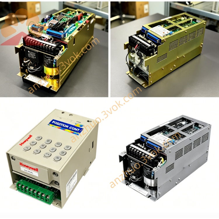
1. Product Overview
2. Core Functional & Electrical Specifications
Operating power supply: DC24V fed from XRC cabinet internal control power source
Main onboard resources: 32-point isolated digital input / 24-point relay-type digital output terminals, dedicated safety interlock signal channel for robot door switch, external emergency stop, robot lockout signal processing
Special interface port: Custom flat cable connector to plug into XSU02 main servo control unit for internal cabinet bus communication
Built-in overcurrent protection fuses per output channel, transient voltage suppression circuit against field surge from welding equipment
Signal isolation design via optocoupler to block external electromagnetic interference from peripheral actuator and solenoid loads
3. Mechanical Installation Details
Standard slot plug-in PCB structure, fixed inside XRC cabinet backplane rack beside JZRCR-XSU02 and XC001 servo boards without extra cabinet modification
PCB dimension: approx W125 × H210 × D25mm, no outer metal casing, natural air cooling relying on cabinet internal airflow
IP00 bare circuit board design, only allowed installation inside sealed robot electrical cabinet to avoid dust, oil mist contamination
4. Compatible Matching Components
Main matching core boards: JZRCR-XSU02 servo mainboard, JZRCR-XC001/XC001B axis servo driver boards
Supporting accessories: XRC cabinet internal DC24V power supply unit, safety relay terminal block, external robot peripheral wiring harness
Interchange remark: MORI-04 is fixed unique model for standard XRC system; no direct alternative replacement board, parameter-free plug-and-play after hardware replacement
5. Working Environment Criteria
Continuous operating ambient temp inside cabinet: 0℃ ~ +50℃; storage temperature: -25℃ ~ +70℃
Working relative humidity: 10%~85%RH non-condensation; prohibit installation nearby cutting fluid vapor, corrosive gas and strong vibration
6. Standard Replacement Operation Steps
Cut off total AC power input of robot control cabinet, wait minimum 15 minutes to discharge residual capacitor voltage for safety before disassembly.
Mark all external field wiring and internal flat bus cables connected on MORI-04 one by one, disconnect all wiring sequentially.
Remove fixed lock screw of old MORI-04 board, insert replacement board into original backplane slot and secure fastening screw tightly.
Reconnect all marked cables strictly following original labeling sequence.
Restore cabinet main power, finish robot system self-check, verify external safety signal (door lock, emergency stop) feedback status and execute manual jog test of robot axes.
7. Common Fault & Troubleshooting
Robot external E-stop / safety door interlock abnormal, system triggers safety lock alarm: Check blown channel fuse on MORI-04 or loose flat cable between MORI-04 and XSU02 mainboard.
Peripheral fixture solenoid / coolant auxiliary output no action: Inspect corresponding DO terminal circuit damage or burnt onboard output relay of MORI-04.
Intermittent random safety fault during automatic running: Clean accumulated dust on PCB surface causing partial short circuit or poor connector contact.
Get a Quote