JZRCR-NTU15C
JZRCR-NTU15C (common suffix variants: NTU15C-2 / NTU15C-3) is Yaskawa Motoman original system control power supply module exclusively designed for NX100 robot controller cabinet, paired with inner PCB board JANCD-NTU01 series. It serves as core auxiliary power unit inside NX100 control cabinet, specially responsible for power supply of main control board, safety circuit, teach pendant and peripheral I/O logic circuit of UP, HP, VA, MA series Motoman six-axis robots. Original OEM production is discontinued; available spare parts on market are tested refurbished or surplus original units for maintenance replacement of aging NX100 equipment.
Description
1. Product Overview
JZRCR-NTU15C (common suffix variants: NTU15C-2 / NTU15C-3) is Yaskawa Motoman original system control power supply module exclusively designed for NX100 robot controller cabinet, paired with inner PCB board JANCD-NTU01 series. It serves as core auxiliary power unit inside NX100 control cabinet, specially responsible for power supply of main control board, safety circuit, teach pendant and peripheral I/O logic circuit of UP, HP, VA, MA series Motoman six-axis robots. Original OEM production is discontinued; available spare parts on market are tested refurbished or surplus original units for maintenance replacement of aging NX100 equipment.
2. Electrical Specifications
Rated input: Single-phase AC200V~230V, 50/60Hz, allowable input voltage fluctuation ±10% of nominal value.After internal high-frequency switching rectification, multiple regulated DC outputs including DC5V and DC24V are provided for full system logic circuits. Built-in complete protection circuits including overcurrent, overvoltage, short-circuit and overheat protection; power output will be automatically shut down once abnormal load occurs to avoid damage to downstream control hardware. Internal EMC filter circuit suppresses power grid surge and servo electromagnetic interference to guarantee stable output voltage.
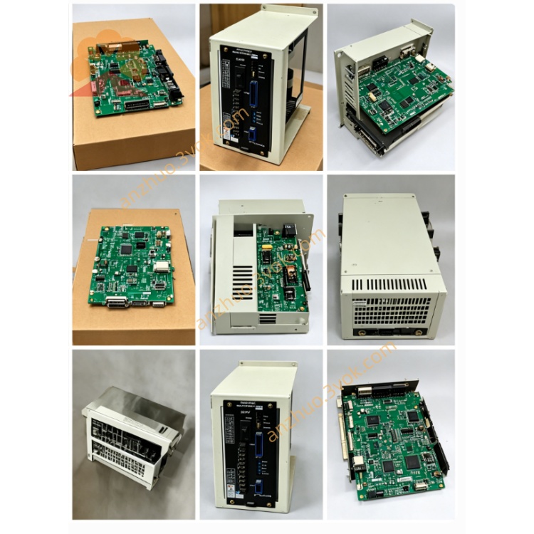
3. Mechanical & Installation Features
Adopts fully enclosed metal shielding shell with passive air cooling slots on housing surface for heat dissipation during continuous operation. Standard embedded fixed installation structure for NX100 cabinet inner rack via mounting screws. Multiple dedicated plug-in terminal connectors are arranged on module side for AC input wiring and multi-group DC output wiring to cabinet main backplane. Shell surface is anti-rust electroplated to adapt long-term dusty workshop cabinet working environment, protection grade IP20 for indoor cabinet mounting only.
4. Compatible Matching Components
Perfectly matched with full NX100 system hardware: main CPU board JANCD-NCP01, servo drive rack, emergency stop safety loop assembly and handheld teach pendant JZRCR-YPP21-1. Cooperates with JZRCR-NTU04 main servo power supply to constitute complete two-stage power distribution framework of NX100 controller; direct plug-and-play replacement without modification on original wiring layout.
5. Operating Environment Parameters
Continuous working ambient temperature inside closed cabinet: 0℃ ~ +55℃; storage temperature after power-off: -20℃ ~ +70℃. Working relative humidity 10%~85% without dew condensation. Installation position must avoid heavy oil mist, corrosive gas, intense mechanical vibration and high-frequency EMI from welding machines and high-power inverters.
6. Replacement Operation Procedures
Cut off total cabinet AC main power and wait over 15 minutes to release residual high voltage inside module for anti-electric-shock protection before disassembly.
Mark all input & output cable positions of original NTU15C module then disconnect all wiring sequentially.
Remove fixing bolts of faulty unit and install new JZRCR-NTU15C at original fixed position firmly.
Restore all connection wires strictly following previous marking records.
Switch on main power supply after installation, complete system power-on self-test and single-axis jog test to confirm no power alarm and normal teach pendant startup.
7. Common Fault Diagnosis & Troubleshooting
Fault 1: Whole system no power-up after energization, all indicators off: Check AC200V input circuit first, inspect blown internal fuse or damaged rectifier circuit inside NTU15C module.Fault 2: Random low-voltage alarm and intermittent shutdown during robot running: Clear dust blocking cooling vents leading to overheat protection, check loose terminal wiring causing unstable power output.Fault3: Teach pendant fails to power on while main control board works normally: Troubleshoot independent DC24V output channel and corresponding terminal damage of this power module.
8. Safety Regulations
Live hot plugging of input/output cables is strictly prohibited; instantaneous surge voltage will permanently destroy internal power circuit and peripheral control boards. All disassembly and maintenance operations must be completed by certified technicians familiar with NX100 control circuit principle. Random modification of internal module wiring without official specification approval is forbidden, which may trigger entire robot control failure and on-site operation safety hazards.
Get a Quote