
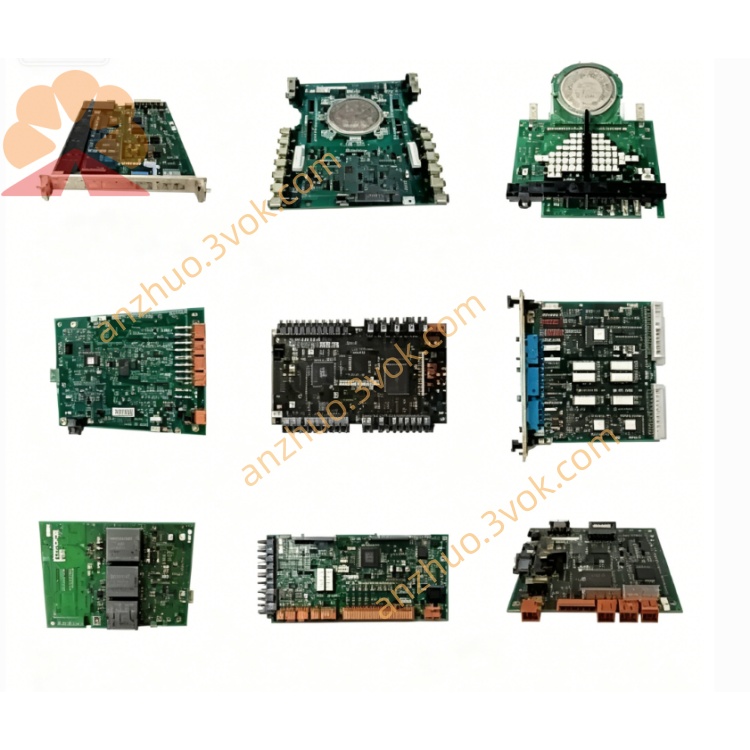
ABB MIRU-01 (part number 3AXD50000033270) insulation resistance measurement unit
Description
Product Introduction
Model Interpretation
MIRU: Measuring Insulation Resistance Unit
01: Standard hardware configuration, revision G
3AXD50000033270: ABB’s formal order part number
Technical Parameters
Supply voltage: 24 V DC
Measurement range: Typically 10 kΩ – 10 MΩ (application-dependent)
Measurement accuracy: ±5% of reading
Operating temperature: −25 °C to +70 °C
Storage temperature: −40 °C to +70 °C
Protection class: IP20
Mounting: 35 mm DIN rail or panel mount
Weight: 1.23 kg
Compliance: CE, RoHS, UL 61010-1
Interface and Connection
Measurement terminals: Screw terminals for connecting to the insulation test object (motor, cable, winding)
Power terminals: 24 V DC input (±)
Status output: Relay contact for alarm (resistance below threshold)
Indicators: Multi‑LED for power, measurement active, and fault/alarm
Internal circuit: Precision resistance bridge, surge protection, and fault diagnostics
Core Functions
Continuous insulation resistance monitoring: Tracks trends over time for predictive maintenance
High‑accuracy measurement: Stable readings under industrial noise conditions
Adjustable alarm threshold: User‑configurable resistance limit for early warning
Fault detection: Identifies short circuits, open circuits, and connection faults
Isolation protection: Galvanic isolation between measurement circuit and system ground
Compact integration: Designed for installation in control cabinets with drives and PLCs
Application Scenarios
Medium‑voltage AC drive systems (ACS800, ACS880, ACQ810)
Motor insulation monitoring in mining, metals, pulp & paper, water treatment
Power cable and transformer insulation health checks
Critical equipment preventive maintenance and condition monitoring
Industrial automation panels and motor control centers (MCC)
Operation and Maintenance Instructions
Install in a dry, well‑ventilated cabinet; avoid dust, moisture, and corrosive gases
Use 1.5–2.5 mm² copper wires for measurement and power connections
Set the alarm threshold according to equipment insulation requirements (typically 1–5 MΩ)
After power‑on, verify LED status: power OK, measurement active
Inspect terminals quarterly for looseness, corrosion, or damage
Keep unit surface clean; avoid covering ventilation slots
Before replacement, disconnect all power and take ESD precautions
No routine calibration required; replace only if measurement error persists
Get a Quote