
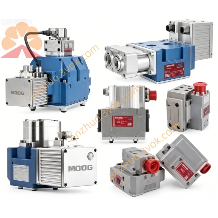
MOOG D634-394C Direct Drive Servo Valve
MOOG D634-394C
Direct Drive Servo Valve (DDV)
ISO 4401 Size 05 (NG10) – 24 VDC Integrated Electronics
Single-stage pilotless ultra-high flow servo valve
Description
1. Model Definition
D634: Direct drive servo valve series with ISO 4401 Size 05 mounting394: Upgraded ultra-high flow specificationC: Revision version C
2. Hydraulic Specifications
Mounting standard: ISO 4401-05 (NG10)Max working pressure of P, A, B ports: 350 barMax pressure of T port without Y port: 50 barMax pressure of T port with Y port: 350 barRated flow at 35 bar pressure drop: 380 L/minMaximum flow rate: approximately 500 L/minInternal leakage: ≤7.0 L/minApplicable fluid: ISO 11158 standard mineral oilFluid temperature range: -20 °C ~ +80 °CRequired fluid cleanliness: ISO 4406 17/14/11Total weight: approximately 9.5 kg
3. Dynamic Performance
Full stroke step response: ≤14 ms-3dB frequency bandwidth: 75~85 HzHysteresis: less than 0.20% full scalePosition resolution: less than 0.10% full scaleNull drift under 55K temperature change: less than 1.2% full scale
4. Electrical Specifications
Supply voltage: 24 VDC, working range 18~32 VDCMaximum operating current: 5.0 AStandard control signal: ±10 VOptional signal: ±10 mA, 4-20 mASpool position feedback output: 0-10 VDCConnector type: M18, 6 pins with PE terminal, IP65 protection gradeAmbient temperature: -20 °C ~ +60 °CEMC certification: CE compliant
5. Key Features
Pilotless direct drive design eliminates auxiliary oil supply demandSuper large flow capacity satisfies extreme heavy load working conditionsPressure independent dynamic performance ensures stable operationBuilt-in LVDT sensor achieves high precision closed-loop position controlSpring centering structure realizes fail-safe protection during power failureIntegrated electronic module owns compact structure and strong anti-interference ability
6. Application Scope
Super heavy-duty hydraulic press and forging extrusion equipmentLarge aerospace and automotive structural test benchesHigh-load vibration simulation and motion simulation platformsPrecision closed-loop position, velocity and pressure control hydraulic systems
7. Pin Assignment
Pin 1: +24 VDC powerPin 2: Power groundPin 3: Command signal positivePin 4: Command signal negativePin 5: Position feedback outputPin 6: Feedback groundPE: Protective earthShielded twisted pair cable is recommended for signal wiring
Get a Quote