
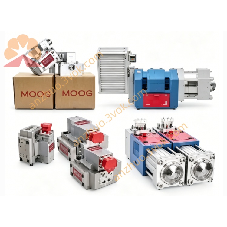
MOOG D634-319CR40K02MONSP2 Direct Drive Servo Valve
Description
1. General Description
2. Model Code Decoding (R40K02MONSP2)
R40: Rated flow 100 L/min (Δp = 35 bar per land)
K: Spool type = 4‑way, linear, 1.5–3% overlap
02: 24 VDC standard electronics, PWM drive
M: Neutral position (spring‑centered on power loss)
0: No Y port; T‑port max 50 bar
N: Seals = NBR (Nitrile Butadiene Rubber)
S: Control signal = ±10 mA
P: Feedback output = 0–10 V (LVDT spool position)
2: Connector = M18, 6+PE pins, IP65Moog Inc.
3. Hydraulic Specifications
Mounting: ISO 4401 Size 05 (NG10)
Max Working Pressure (P, A, B): 350 bar (5,000 psi)
T‑Port Pressure: 50 bar (no Y port)
Rated Flow (Δp = 35 bar/land): 100 L/min (26.4 gpm)
Max Flow: ≈180 L/min (47.6 gpm)
Internal Leakage: ≤1.2 L/min
Fluid: Mineral oil (ISO 11158)
Fluid Temperature: −20 °C to +80 °C
Filtration: ISO 4406 17/14/11
Weight: ≈6.3 kg (13.9 lb)Moog Inc.
4. Dynamic Performance (Typical)
Step Response (0→100% stroke): ≤18 ms
−3 dB Bandwidth: 55–65 Hz
Hysteresis: <0.2% FS
Resolution: <0.1% FS
Null Drift (ΔT = 55 K): <1.5% FSMoog Inc.
5. Electrical Specifications (R40K02MONSP2)
Supply Voltage: 24 VDC (18–32 VDC)
Max Current: 3.5 A
Control Signal: ±10 mA
Feedback Output: 0–10 VDC (spool position)
Connector: M18, 6+PE pins, IP65
Ambient Temperature: −20 °C to +60 °C
EMC: CE compliantMoog Inc.
6. Key Features
Pilotless direct drive: 100 L/min rated flow; no external pilot supply
Closed‑loop LVDT control: High precision and repeatability
Pressure‑independent response: Stable dynamics under varying load pressures
Fail‑safe spring centering: Returns to neutral on power loss
Compact, rugged build: Suits harsh industrial environments
7. Applications
High‑flow hydraulic presses
Large material fatigue test benches
Industrial automation (high‑flow position/velocity/pressure control)
General high‑response closed‑loop hydraulic systems
8. Pin Assignment (M18, 6+PE)
+24 VDC
Power GND
Command +
Command −
Position Feedback Out
Feedback GND
PE: Protective Earth
Recommendation: Use shielded twisted‑pair cable for signals.
9. Installation & Operation Notes
System Flushing: Flush system to ISO 4406 15/12 or better before valve installation.
Mounting: Install on clean, flat surface; torque mounting bolts to manufacturer’s specs.
Wiring: Use shielded cables; separate power and signal wires to avoid noise.
Filtering: Maintain system filtration at ISO 4406 17/14/11 to prevent wear.
Temperature: Keep fluid within −20 °C to +80 °C; avoid thermal shock.
10. Maintenance & Troubleshooting
Regular Checks: Inspect for leaks, loose connections, and abnormal noise.
Filter Replacement: Replace pressure filters per schedule to maintain cleanliness.
No Response: Check power supply, wiring, and command signal; verify LVDT feedback.
Drift/Instability: Check fluid contamination, temperature, or mechanical wear.
11. Safety Instructions
Pressure Relief: Relieve system pressure before installation or maintenance.
Electrical Safety: Disconnect power before wiring; avoid contact with live parts.
High Pressure: Do not disconnect hoses under pressure; use proper safety equipment.
Environmental: Do not expose to explosive or corrosive atmospheres unless rated.
Get a Quote