
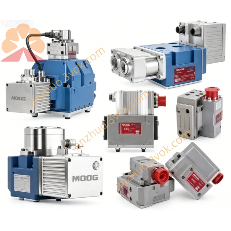
MOOG D634-1045 Direct Drive Servo Valve
D634-1045 is a single-stage direct drive servo valve. It adopts integrated 24VDC electronic module and LVDT closed-loop spool position feedback. Driven by permanent magnet linear force motor without pilot oil supply, the valve features spring centering structure and automatically returns spool to neutral position when power fails. This model delivers high flow capacity and excellent dynamic performance, suitable for high-speed hydraulic presses, dynamic material testing benches and high precision closed-loop motion control systems.
Description
1. General Description
D634-1045 is a single-stage direct drive servo valve. It adopts integrated 24VDC electronic module and LVDT closed-loop spool position feedback. Driven by permanent magnet linear force motor without pilot oil supply, the valve features spring centering structure and automatically returns spool to neutral position when power fails. This model delivers high flow capacity and excellent dynamic performance, suitable for high-speed hydraulic presses, dynamic material testing benches and high precision closed-loop motion control systems.
2. Hydraulic Specifications
Maximum working pressure of port P, A and B is 350 bar. Port T withstands 50 bar pressure without Y drain port, and 350 bar pressure with Y port connected. Rated flow reaches 100 liters per minute under 35 bar pressure drop. Maximum flow capacity is approximately 190 liters per minute. Internal leakage is limited within 0.55 liters per minute.
Applicable fluid is mineral hydraulic oil complying with ISO 11158 and DIN 51524 standards. Fluid operating temperature ranges from -20°C to 80°C. System oil cleanliness shall maintain ISO 4406 17/14/11 grade to ensure stable operation.
3. Performance Characteristics
Full stroke step response time is 10 to 12 milliseconds. -3dB frequency response ranges from 108 to 118 hertz. Hysteresis error is less than 0.38% full scale. Positioning resolution is better than 0.09% full scale. Null thermal drift is below 0.8% full scale under 60 Kelvin temperature variation. Position repeatability is controlled within 0.22% full scale.
4. Electrical Specifications
Nominal power supply is 24VDC with voltage tolerance from 18VDC to 32VDC. Maximum operating current is 3.5 amperes. Three control signal modes ±10V, ±10mA and 4-20mA are selectable via internal jumper. Standard 0-10VDC spool position feedback signal is equipped.
The valve is fitted with M18 connector with 6 signal pins and protective earth terminal, IP65 protection degree. Ambient working temperature covers -20°C to 60°C. All electronic parts meet CE electromagnetic compatibility requirements.
5. Working Principle
LVDT sensor detects real-time spool displacement and transmits feedback signal to internal circuit. Electronic unit compares command signal with actual position data, then outputs drive signal to linear force motor. The motor drives spool movement to adjust flow rate and direction, realizing accurate hydraulic control. Spring structure guarantees safe reset during power outage.
6. Installation Instructions
Install the valve on flat and clean mounting surface according to ISO 4401 Size 05 standard. Fasten bolts with specified torque, avoid mechanical impact and installation deviation. Horizontal installation is recommended for air exhaust. Fully bleed residual air inside valve and pipelines before official operation.
7. Wiring Definition
Pin 1: +24VDC powerPin 2: Power groundPin 3: Command signal positivePin 4: Command signal negativePin 5: Spool position feedback outputPin 6: Feedback groundPE terminal: Protective earth connectionShielded twisted pair cable is required for signal wiring.
8. Maintenance Notes
This valve is sealed integrated structure without removable internal maintenance components. Regularly check oil contamination and replace filter elements timely. Inspect connector condition periodically to prevent damage and corrosion. Unauthorized disassembly is forbidden and will void product warranty.
Get a Quote