
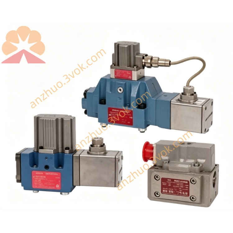
MOOG D634-1034 Direct Drive Servo Valve
Description
1. General Description
Series: D634 (ISO 4401 Size 05 / NG10)
Model 1034: ultra‑high‑flow, standard‑dynamic response, low‑leakage
Applications: High‑speed/high‑force hydraulic presses; dynamic material testing; flight simulators; industrial motion control requiring maximum flow + stability.
2. Hydraulic Specifications
- Max working pressure (P, A, B): 350 bar (5,000 psi)Moog Inc.
- Port T pressure: 50 bar (725 psi) (without Y port); 350 bar (5,000 psi) (with Y port)Moog Inc.
- Rated flow (Δp = 35 bar/land): 125–135 L/min (33.0–35.7 gpm)
- Max flow: approx. 250 L/min (66.0 gpm)
- Internal leakage: ≤0.50 L/min (low‑leakage version)
- Operating fluid: Mineral oil per ISO 11158 / DIN 51524
- Fluid temperature: −20 °C to +80 °C
- Recommended cleanliness: ISO 4406 17/14/11
3. Performance Characteristics
Step response (0→100%): 16–18 ms
Frequency response (−3 dB): ≥75–85 Hz
Hysteresis: <0.45% FS
Resolution: <0.12% FS
Null drift (ΔT = 60 K): <1.1% FS
Repeatability: <0.30% FS
4. Electrical Specifications
Supply: 24 VDC (18–32 VDC)Moog Inc.
Max current: 4.0 A
Control signals (jumper selectable): ±10 V, ±10 mA, 4–20 mAMoog Inc.
Feedback: 0–10 VDC spool position output
Connector: M18, 6+PE, IP65Moog Inc.
Ambient temperature: −20 °C to +60 °C
EMC: Compliant with CE directives
5. Working Principle
6. Installation Instructions
Mount on a clean, flat surface per ISO 4401‑05 mounting pattern.
Torque mounting bolts to manufacturer specs; avoid impact or misalignment.
Install horizontally for optimal air bleeding.
Bleed all air from valve and piping before operation.
7. Wiring Definition
Pin 1: +24 VDC
Pin 2: Power GND
Pin 3: Command +
Pin 4: Command −
Pin 5: Feedback Out
Pin 6: Feedback GND
PE: Protective Earth (frame ground)
Use shielded twisted‑pair cables for signals.
8. Maintenance Notes
Sealed integral construction; no user‑serviceable internal parts.
Monitor fluid contamination; replace filters regularly to maintain ISO 4406 17/14/11 cleanliness.
Inspect connector and cables periodically for damage or corrosion.
Unauthorized disassembly voids warranty.
Get a Quote