
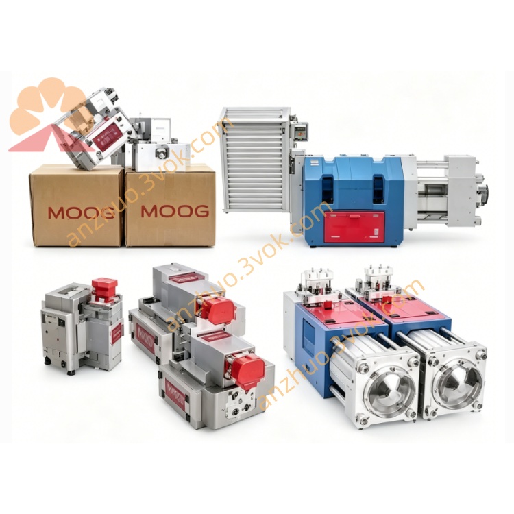
MOOG D634-1024 Direct Drive Servo Valve
Description
1. GENERAL DESCRIPTION
Series: D634 (ISO 4401 Size 05 / NG10)
Model: 1024 = High‑flow, high‑dynamic response version
Design: 4‑way, spring‑centered, zero‑lap spool
Applications: High‑speed injection molding, hydraulic presses, machine tools, and high‑precision closed‑loop motion control systems.
2. HYDRAULIC SPECIFICATIONS
| Parameter | Value |
|---|---|
| Max pressure (P, A, B) | 350 bar (5,000 psi)Moog Inc. |
| Port T (without Y) | 50 bar (725 psi)Moog Inc. |
| Port T (with Y) | 350 bar (5,000 psi)Moog Inc. |
| Rated flow (Δp = 35 bar/land) | 70–90 L/min (18.5–23.8 gpm) |
| Max flow | ≈180 L/min (47.5 gpm) |
| Internal leakage | ≤0.40 L/min |
| Fluid type | Mineral oil ISO 11158 / DIN 51524 |
| Fluid temperature | −20 °C … +80 °C |
| Recommended cleanliness | ISO 4406 17/14/11 |
3. PERFORMANCE (TYPICAL)
| Parameter | Value |
|---|---|
| Step response (0 → 100%) | ≈14 ms |
| Frequency response (−3 dB) | ≥90 Hz |
| Hysteresis | <0.35% FS |
| Resolution | <0.10% FS |
| Null drift (ΔT = 60 K) | <0.9% FS |
| Repeatability | <0.15% FS |
4. ELECTRICAL SPECIFICATIONS
| Parameter | Value |
|---|---|
| Supply voltage | 24 VDC (18–32 VDC)Moog Inc. |
| Max current | 2.7 A |
| Control signal (jumper select) | ±10 V, ±10 mA, 4–20 mAMoog Inc. |
| Spool feedback output | 0–10 VDC |
| Connector | M18, 6+PE, IP65Moog Inc. |
| Ambient temperature | −20 °C … +60 °C |
| EMC compliance | CE (EN 61000‑6‑2, EN 61000‑6‑4) |
5. FUNCTIONAL PRINCIPLE
Closed‑loop spool control: An LVDT continuously measures spool position; the integrated electronics compare it to the command signal and drive the linear motor to eliminate position error.
Force motor: Permanent magnet linear motor provides bidirectional force for fast, precise spool positioning.
Fail‑safe: Spring‑centered design returns spool to neutral on power loss.
6. INSTALLATION & MOUNTING
Mounting pattern: ISO 4401‑05‑05‑0‑94
Mounting surface: Flat, clean, roughness Ra ≤ 3.2 μm
Torque: M6 bolts → 9–11 Nm
Orientation: Any (horizontal preferred for best drainage)
Venting: Remove air from valve and lines before operationMoog GmbH.
7. WIRING DIAGRAM (M18 6+PE)
| Pin | Function |
|---|---|
| 1 | +24 VDC |
| 2 | 0 VDC (GND) |
| 3 | Command signal (+) |
| 4 | Command signal (−) |
| 5 | Feedback output (0–10 V) |
| 6 | Feedback GND |
| PE | Protective earth |
8. MAINTENANCE
No internal maintenance – sealed for life.
Check fluid cleanliness regularly (ISO 17/14/11).
Inspect electrical connector for damage or corrosion.
Do not disassemble – warranty void if opened.
9. ORDERING CODE (EXCERPT)
1024 = High‑flow, high‑dynamic response
Next digits = signal type, feedback, sealing, etc.
10. RELATED DOCUMENTS
Moog D633/D634 Series User Manual (English)
D634‑1024 Datasheet
Installation Drawing DWG‑D634‑05
Get a Quote