
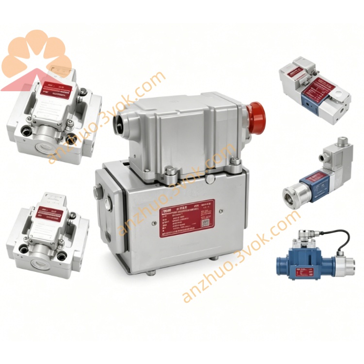
MOOG D634-1013 Direct Drive Servo Valve
This unit belongs to MOOG D634 series single stage direct drive servo valve. It adopts ISO 4401 Size 05 mounting dimension. Equipped with integrated 24VDC electronic drive unit and LVDT closed-loop spool position feedback. Model 1013 is designed for steady and smooth control performance with low running noise, suitable for common high precision hydraulic control occasions.
Description
General Information
This unit belongs to MOOG D634 series single stage direct drive servo valve. It adopts ISO 4401 Size 05 mounting dimension. Equipped with integrated 24VDC electronic drive unit and LVDT closed-loop spool position feedback. Model 1013 is designed for steady and smooth control performance with low running noise, suitable for common high precision hydraulic control occasions.
Hydraulic Specifications
Maximum working pressure of pressure port and working ports is 350 bar. Return port withstands 50 bar pressure without external drain port, and reaches 350 bar when drain port is connected. Rated flow is 60 to 100 liters per minute under 35 bar pressure difference. Maximum flow capacity is 185 liters per minute. Internal leakage is limited below 0.45 liters per minute.
Applicable working medium is mineral hydraulic oil conforming to ISO 11158 and DIN 51524 standards. Operating fluid viscosity ranges from 5 to 400 square millimeters per second, recommended viscosity scope is 15 to 100 square millimeters per second. Fluid working temperature covers -20 degrees Celsius to 80 degrees Celsius. Required oil cleanliness grade is ISO 4406 18/15/12, 17/14/11 is suggested for longer service life.
Control Performance
Typical full stroke step response time is 20 milliseconds. Hysteresis value is less than 0.4 percent full scale. Control resolution is better than 0.10 percent full scale. Null position drift is lower than 1.0 percent under 60 Kelvin temperature variation. Negative 3dB frequency response is no less than 70 hertz.
Electrical Parameters
Nominal power supply is 24 volt direct current, acceptable voltage range is 18 to 32 volt direct current. Maximum operating current is 2.2 ampere. External 2.5 amp slow blow fuse is recommended for circuit protection.
Available control signal types include ±10 volt voltage signal, ±10 milliampere current signal and 4 to 20 milliampere current signal, signal mode can be switched via internal jumper. Input impedance is over 100 kiloohm for voltage signal and 50 ohm for current signal. Standard 0 to 10 volt spool position feedback signal is available. Electrical connector is M18 type with six pins and protective earth terminal, protection class is IP65. Ambient working temperature ranges from -20 degrees Celsius to 60 degrees Celsius.
Main Features
Stable motion performance realizes low vibration and low noise operation. Closed-loop position feedback ensures reliable repeated control accuracy. Spring centering structure automatically resets spool when power fails. Integrated electronic design simplifies field wiring and installation. Strong pressure resistance adapts to heavy load industrial hydraulic system.
Working Principle
External analog command signal transmits to internal electronic module. Drive signal pushes linear force motor to displace valve spool. LVDT sensor collects real-time spool position data and sends feedback signal. Control circuit compares set value and actual position, adjusts output to achieve accurate spool positioning. Spool displacement changes hydraulic flow area and direction, thereby controlling the running speed and direction of hydraulic actuators.
Installation and Connection
Fix the valve on flat and clean mounting surface according to standard installation holes. Install matched sealing rings and fasten M8 mounting bolts with torque of 8 to 10 newton meter. Avoid mechanical impact and installation deviation.
Connect oil pipelines correctly, pressure port connects oil supply line, return port links fuel tank, working ports connect hydraulic cylinder cavities. External drain port shall be connected to low pressure return pipeline. Flush the whole hydraulic system to qualified cleanliness before formal operation.
Apply shielded twisted cable for signal connection. Pin 1 connects 24VDC positive pole, pin 2 connects power ground, pin 3 and pin 4 are command signal terminals, pin 5 is enable terminal, pin 6 outputs position feedback signal, keep reliable grounding for protective terminal.
Commissioning and Operation
Check mechanical fastening, pipeline and circuit connection condition before power on. Confirm power voltage and fluid level meet working requirements. The valve completes self-check and initialization automatically after power supply. Select applicable signal mode according to on-site control demand. Adjust null position to minimize internal leakage under zero command input.
Zero control signal keeps spool at middle position without hydraulic output. Positive full scale signal makes fluid flow from port A to port B, negative signal realizes reverse flow direction. Real-time spool stroke state can be monitored through feedback signal.
Maintenance and Troubleshooting
Carry out regular inspection for external oil leakage and loose wiring every month. Replace filter elements periodically to maintain qualified oil cleanliness level. Replace aging sealing parts with original MOOG accessories once leakage occurs. Disassembly of internal precision components is forbidden without official permission.
No actuator movement usually results from power failure, broken circuit or missing control signal. Slow response speed is caused by insufficient system pressure, excessive fluid viscosity or contaminated oil. System instability and oscillation relate to electromagnetic interference and improper control parameter setting. Replace damaged sealing rings to solve oil leakage fault.
Application Range
Suitable for ordinary injection molding machine, heavy load hydraulic press, metal forming equipment and material mechanical test bench. Widely used in industrial servo hydraulic systems which take operation stability and low noise as priority requirements.
Get a Quote