
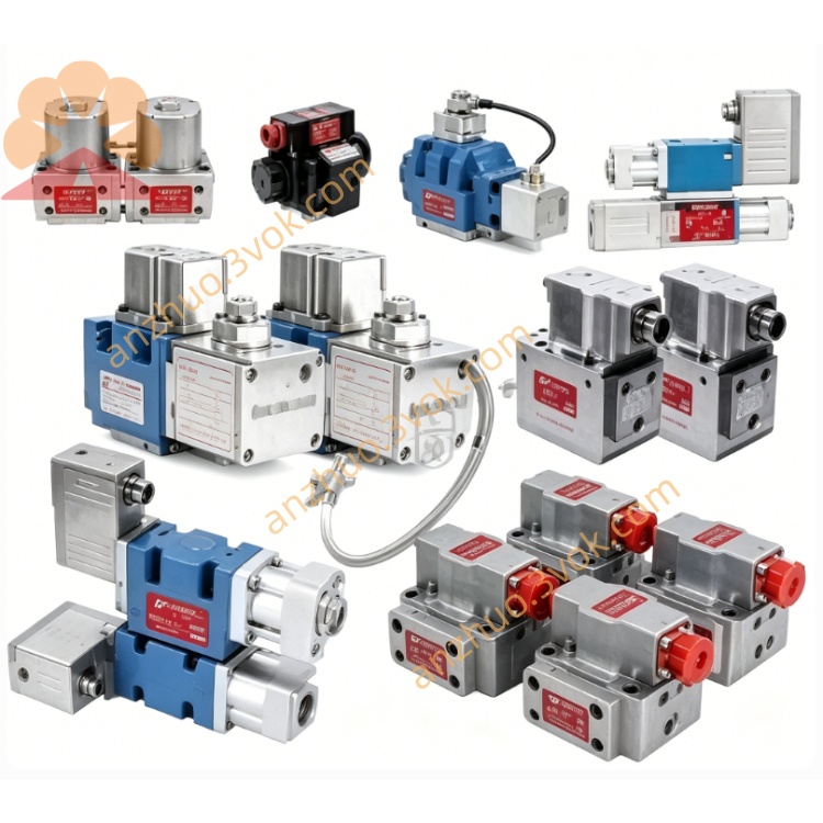
MOOG D634-1010 Direct Drive Servo Valve
Description
1. General Information
1.1 Description
1.2 Model Definition
D634: ISO 4401 Size 05, direct‑drive, integrated 24 VDC electronics, analog interface servo valve.
1010: Suffix defines coil parameters, LVDT range, seal material, electronic gain/offset, and performance tuning (1010: optimized for ultra‑low noise, exceptional long‑term stability, and minimal thermal drift; targeted at precision closed‑loop control).
1.3 Key Features
Single‑stage direct drive: no pilot supply needed, better contamination tolerance, simpler system.
Pressure‑independent dynamics: consistent response at any system pressure.
Integrated EMC‑compliant 24 VDC electronics: reduces external components, simplifies installation.
Spring‑centered fail‑safe: spool returns to neutral on power loss, stopping actuators.
Low hysteresis & high resolution: hysteresis <0.3%, resolution <0.08% full scale (best‑in‑class).
1010 specific: Ultra‑low electrical noise, minimal thermal null shift, enhanced long‑term stability for precision applications.
1.4 Intended Applications
2. Technical Specifications
2.1 Hydraulic Data
Mounting: ISO 4401 Size 05 (NG10).
Max operating pressure (P, A, B): 350 bar (5,000 psi).
Port T pressure: 50 bar (725 psi) without Y port; 350 bar (5,000 psi) with Y portMoog Inc..
Rated flow (Δp = 35 bar per land): 60–100 L/min (15.9–26.4 gpm).
Maximum flow: approx 185 L/min (48.8 gpm).
Internal leakage: ≤0.4 L/min (1010, lowest in D634 series).
Operating fluid: mineral oil per ISO 11158 / DIN 51524 parts 1–3.
Recommended viscosity: 15–100 mm²/s; allowable 5–400 mm²/s.
Fluid temperature: −20 °C to +80 °C.
Fluid cleanliness: ISO 4406 18/15/12 min; 17/14/11 recommended.
2.2 Performance Data
Step response (0–100% stroke): typically 9–13 ms (1010).
Hysteresis: <0.3% full scale (improved vs 1009 <0.5%).
Threshold (resolution): <0.08% full scale (improved vs 1009 <0.1%).
Null shift (ΔT = 55 K): <0.8% (1010, best‑in‑class).
Frequency response (−3 dB): ≥105 Hz (1010); higher than 1009 (≥100 Hz).
2.3 Electrical Data
Supply voltage: 24 VDC (operating range 18–32 VDC)Moog Inc..
Max current consumption: 2.2 A.
Recommended fuse: 2.5 A slow‑blow (external).
Command signal options: ±10 V, ±10 mA, 4–20 mA (selectable via internal jumper)Moog Inc..
Input impedance: >100 kΩ (voltage); 50 Ω (current).
Spool position monitor: 0–10 VDC output (standard).
Connector: 6+PE (M18), IP65Moog Inc..
Ambient temperature: −20 °C to +60 °C.
3. Functional Principle
4. Installation & Wiring
4.1 Mechanical Mounting
4.2 Hydraulic Connections
P: Pressure supply
T: Tank return
A/B: Work ports
Y: Optional external drain
4.3 Electrical Wiring (6+PE Connector)
Pin 1: +24 VDC
Pin 2: 0 VDC (GND)
Pin 3: Command (+)
Pin 4: Command (−)
Pin 5: Enable (optional)
Pin 6: Spool position monitor
PE: Protective earth
5. Commissioning
Verify mechanical, hydraulic, and electrical connections before power‑up.
Confirm fluid level and supply voltage (18–32 VDC).
Apply 24 VDC power; valve initializes and performs LVDT self‑test.
Select command signal type via internal jumper.
With zero command, adjust null potentiometer for minimum leakage.
Apply 10%, 50%, 100% step commands to verify smooth response, correct direction, and stability.
6. Operation
0 V / 0 mA / 12 mA: spool centered, no flow.
+10 V / +10 mA / 20 mA: full flow A→B.
−10 V / −10 mA / 4 mA: full flow B→A.
Monitor pin: 0–10 VDC proportional to spool stroke (diagnostics).
7. Maintenance & Troubleshooting
7.1 Maintenance
Monthly: inspect for external leakage and loose connections.
Replace filters regularly to maintain ISO 4406 18/15/12 cleanliness.
Use genuine MOOG O‑rings for seals.
Do not disassemble internal components; contact MOOG or authorized service centers for repair.
7.2 Troubleshooting
No response: check 24 VDC power, wiring, and command signal.
Slow response: verify system pressure, fluid viscosity, and filtration.
Oscillation/instability: improve shielding, adjust controller gains, check grounding.
External leakage: replace worn O‑rings with genuine MOOG parts.
8. Ordering Information
Model: D634‑1010
Series: D634 (Direct Drive Servo Valve)
Mounting: ISO 4401 Size 05 (NG10)
Electronics: 24 VDC integrated, analog interface
Feedback: LVDT closed‑loop spool position control
Key Differentiator: Ultra‑low noise, minimal thermal drift, highest stability & resolution in D634 series
Get a Quote