
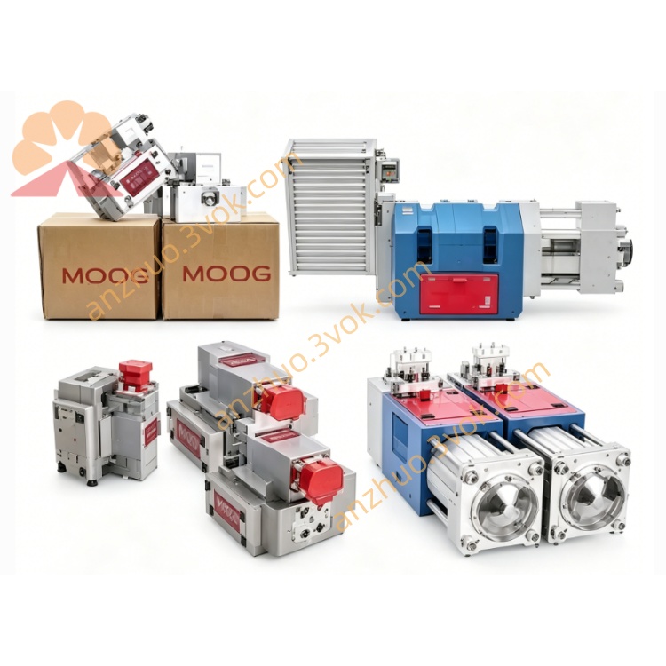
MOOG D634-1007 Direct Drive Servo Valve
D634-1007 belongs to MOOG D634 series single stage direct drive servo valve. It adopts permanent magnet linear force motor structure, equipped with built-in LVDT position feedback and integrated 24VDC drive electronics. The valve follows ISO 4401 size 05 installation standard, applied to closed loop hydraulic control systems for position, speed, pressure and force regulation.
Description
1. General Introduction
D634-1007 belongs to MOOG D634 series single stage direct drive servo valve. It adopts permanent magnet linear force motor structure, equipped with built-in LVDT position feedback and integrated 24VDC drive electronics. The valve follows ISO 4401 size 05 installation standard, applied to closed loop hydraulic control systems for position, speed, pressure and force regulation.
This model code stands for specific coil structure, sealing configuration and internal parameter calibration, matching high precision industrial working conditions.
Core advantages include pilot-less structure with strong anti-pollution ability, stable dynamic performance irrelevant to working pressure, power-off spring centering safety design, low hysteresis and high repeated positioning accuracy.
Typical application scenes cover die casting machine, injection molding equipment, hydraulic forming press, material fatigue test bench and heavy-duty servo hydraulic machinery.
2. Technical Parameters
Standard installation dimension complies with ISO 4401 size 05 specification. Maximum working pressure of pressure port and two working ports reaches 350 bar. Return port pressure is limited within 50 bar without external drain passage, and can bear 350 bar pressure when external drain port is connected.
Nominal flow value keeps 60 to 100 liters per minute under 35 bar pressure difference, maximum flow capacity is about 185 liters per minute. Internal leakage volume is controlled below 0.8 liters per minute.
Applicable working medium is standard industrial mineral hydraulic oil. Permitted fluid viscosity ranges 5 to 400 square millimeters per second, optimal using viscosity is 15 to 100 square millimeters per second. Working fluid temperature scope is from minus 20 degrees Celsius to 80 degrees Celsius. System oil cleanliness shall not lower than ISO 4406 18/15/12 grade.
Full stroke step response time maintains around 20 milliseconds. Hysteresis error is less than 0.5 percent full scale, control resolution is better than 0.1 percent full scale. Temperature drift value stays below 2 percent under 55 Kelvin temperature variation, minus 3dB frequency response exceeds 80 hertz.
Rated power supply is 24 volt direct current, allowable input voltage fluctuation range 18 to 32 volt direct current. Maximum working current consumption is 2.2 ampere, external matching fuse adopts 2.5 amp slow blow type.
Available control signal types contain minus ten volt to plus ten volt voltage signal, minus ten milliampere to plus ten milliampere current signal and 4 to 20 milliampere current signal, selected through internal jumper setting. Electrical interface adopts 6 pins plus grounding M18 connector, protection grade reaches IP65. Ambient working temperature ranges minus 20 degrees Celsius to 60 degrees Celsius.
3. Working Principle
External control command signal transmits to internal integrated circuit module. The electronic unit drives linear force motor to push valve spool depart from middle balance position. Built-in LVDT displacement sensor real-time collects spool position data and feeds back to control loop.
Control circuit compares actual position feedback value with target command value, automatically adjust driving output to realize accurate spool position locking. Spool displacement changes hydraulic flow passing area and flow direction, so as to control the movement speed and direction of hydraulic actuators.
4. Installation and Connection
Place the valve on smooth and clean mounting surface according to standard installation hole position. Install matching sealing rings on mounting surface, fasten M8 fixing bolts with torque 8 to 10 newton meter. Avoid extrusion deformation and position deviation during installation process.
Distinguish each oil port function correctly, pressure port connects oil supply pipeline, return port links oil tank, two working ports connect hydraulic cylinder two chambers, external drain port connects low pressure oil return circuit when needed. Complete pipeline flushing work to reach qualified cleanliness before formal oil filling operation.
Adopt shielded twisted wire for signal wiring. Correspond each pin definition correctly, pin 1 connects positive 24 volt power, pin 2 connects power ground, pin 3 and pin 4 are positive and negative ends of control signal, pin 5 serves as enabling terminal, pin 6 outputs spool position feedback signal, external grounding terminal ensures safe grounding.
5. Commissioning Operation
Check mechanical fastening state, oil pipeline connection and circuit wiring completeness before power supply. Confirm power voltage and liquid level meet operating requirements. Switch on power supply, the valve automatically completes internal self-check initialization procedure.
Set corresponding signal mode according to actual control signal type. Keep zero control signal input, fine adjust neutral point to minimize internal leakage. Input different proportion command signals step by step, inspect movement stability, response speed and action direction correctness.
Zero command signal keeps spool at middle position without hydraulic output. Positive full scale signal outputs fluid flow from A port to B port, negative full scale signal realizes reverse flow control. Feedback signal can monitor real-time spool travel state.
6. Daily Maintenance and Fault Handling
Regularly check outer surface oil leakage and wiring tightness periodically. Replace filter element regularly to guarantee oil cleanliness standard. Replace aging sealing parts with original accessories once leakage appears. Prohibit unauthorized disassembly of internal precision components.
No actuator movement is mainly caused by power failure, broken circuit or missing control signal, inspect power loop and signal line connection. Slow action response results from insufficient system pressure, excessive oil viscosity or oil contamination, adjust working parameters and maintain oil quality.
System vibration and unstable operation relate to electromagnetic interference and improper control parameter matching, optimize shielding grounding condition and adjust controller gain value. Oil leakage failure mostly comes from damaged sealing rings, carry out seal replacement maintenance.
7. Product Information
Model designation D634-1007, classification direct drive electro hydraulic servo valve, installation specification ISO 4401 size 05, built-in 24VDC electronic drive and LVDT closed loop position feedback system.
Get a Quote