
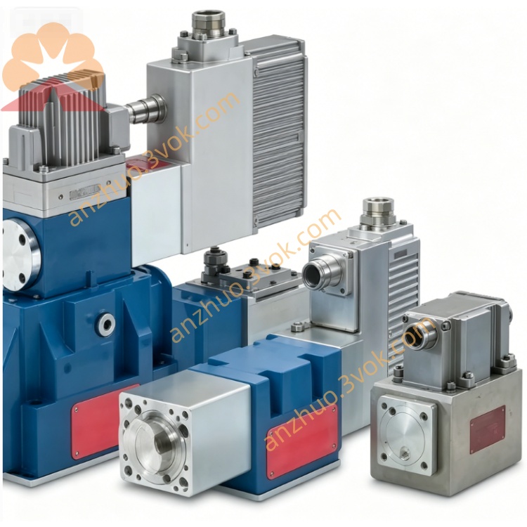
MOOG D634-1001 Direct Drive Servo Valve
Description
1. General Information
1.1 Description
1.2 Model Definition
D634: Series (ISO 4401 Size 05 / NG10)
1001: Specific configuration (coil, feedback, seals, electronics)
1.3 Key Features
No pilot stage: Direct spool drive, high contamination tolerance
Pressure‑independent dynamics: Fast, consistent response
Integrated 24 VDC PWM electronics: EMC‑compliant
Spring‑centered fail‑safe: Spool returns to neutral on power lossMoog Inc.
Low hysteresis & high resolution: Precise, repeatable control
1.4 Intended Applications
2. Technical Specifications
2.1 Hydraulic Data
| Parameter | Value |
|---|---|
| Mounting Pattern | ISO 4401 Size 05 (NG10) |
| Max Operating Pressure (P/A/B) | 350 bar (5,000 psi)Moog Inc. |
| Max Pressure (T, without Y) | 50 bar (725 psi)Moog Inc. |
| Max Pressure (T, with Y) | 350 bar (5,000 psi)Moog Inc. |
| Rated Flow (Δp = 35 bar/land) | 60–100 L/min (15.9–26.4 gpm) |
| Maximum Flow | ~185 L/min (48.8 gpm)Moog Inc. |
| Internal Leakage | ≤ 0.8 L/min |
| Fluid Type | Mineral oil (ISO 11158) |
| Viscosity Range | 5–400 mm²/s (recommended: 15–100 mm²/s) |
| Fluid Temperature | −20 °C to +80 °C |
| Fluid Cleanliness | ISO 4406 18/15/12 min (17/14/11 recommended) |
2.2 Performance Data
| Parameter | Value |
|---|---|
| Step Response (0→100%) | 20 ms (typical)Moog Inc. |
| Hysteresis | < 0.5% of full scale |
| Threshold (Resolution) | < 0.1% of full scale |
| Null Shift (ΔT = 55 K) | < 2% |
| Frequency Response (−3 dB) | ≥ 80 Hz (typical) |
2.3 Electrical Data
| Parameter | Value |
|---|---|
| Supply Voltage | 24 VDC (range: 18–32 VDC)Moog Inc. |
| Current Consumption | 2.2 A max |
| External Fuse | 2.5 A (slow‑blow) |
| Command Signal (selectable) | ±10 V, ±10 mA, 4–20 mAMoog Inc. |
| Input Impedance | Voltage: >100 kΩ; Current: 50 Ω |
| Feedback Signal | Spool position monitor (standard) |
| Connector | 6+PE (M18)Moog Inc. |
| Protection Class | IP65 |
| Ambient Temperature | −20 °C to +60 °C |
3. Functional Principle
Command Input: Analog signal (±10 V / ±10 mA / 4–20 mA) is sent to the valve’s integrated electronics.
Force Motor Drive: Electronics drive a permanent magnet linear force motor to move the spool from spring center.
LVDT Feedback: An LVDT measures spool position and feeds it back to the controller.
Closed‑Loop Control: Electronics compare command vs. feedback and adjust motor drive for precise positioning.
Flow Control: Spool displacement regulates flow direction (A→B / B→A) and magnitude to the actuator.
4. Installation & Wiring
4.1 Mechanical Mounting
Mount on clean, flat surface per ISO 4401 Size 05.
Use supplied O‑rings for port sealing.
Torque mounting bolts (M8) to 8–10 Nm.
Avoid mechanical stress or misalignment.
4.2 Hydraulic Connections
P = Pressure, T = Tank, A/B = Work ports, Y = External drain (optional)Moog Inc..
Flush system to achieve ISO 4406 17/14/11 before valve installation.
4.3 Electrical Wiring (6+PE Connector)
| Pin | Description |
|---|---|
| 1 | +24 VDC |
| 2 | 0 VDC (GND) |
| 3 | Command Signal (+) |
| 4 | Command Signal (−) |
| 5 | Enable (optional) |
| 6 | Monitor (spool position feedback) |
| PE | Protective Earth |
Use shielded twisted pair for signals; connect shield to 0 V (power supply side) and connector housing.
5. Commissioning
Pre‑Check: Verify all connections, fluid level, and supply voltage (18–32 VDC)Moog Inc..
Power‑Up: Apply 24 VDC; valve initializes and performs LVDT self‑test.
Signal Selection: Set command signal type (±10 V / ±10 mA / 4–20 mA) via internal jumperMoog Inc..
Null Adjustment: With zero command, adjust null potentiometer for minimum leakage.
Performance Test: Apply step commands (10% / 50% / 100%); confirm smooth response and correct direction.
6. Operation
0 V / 0 mA / 12 mA: Spool centered (no flow)Moog Inc..
+10 V / +10 mA / 20 mA: Full flow A→BMoog Inc..
−10 V / −10 mA / 4 mA: Full flow B→AMoog Inc..
Monitor Pin: Reads spool position feedback (0–10 V proportional to stroke).
7. Maintenance & Troubleshooting
7.1 Maintenance
Inspect for external leakage and loose connections monthly.
Replace system filters to maintain ISO 4406 18/15/12 cleanliness.
Replace O‑rings with genuine MOOG parts if leakage occurs.
7.2 Troubleshooting
| Symptom | Possible Cause | Remedy |
|---|---|---|
| No response | No 24 VDC power / faulty wiring | Check supply and connectionsMoog Inc. |
| No command signal | Verify signal source and wiringMoog Inc. | |
| Slow response | Low system pressure | Increase pressure to rated levelMoog Inc. |
| High fluid viscosity | Use recommended viscosity fluid | |
| Oscillation | Electrical noise | Improve shielding/grounding |
| Incorrect loop gain | Adjust controller gains | |
| Leakage | Worn O‑rings | Replace sealsMoog Inc. |
8. Ordering Information
Model: D634‑1001
Series: D634 (Direct Drive Servo Valve)Moog Inc.
Size: ISO 4401 Size 05 (NG10)
Electronics: Integrated 24 VDC, analog interfaceMoog Inc.
Feedback: LVDT closed‑loop spool position control
Get a Quote