
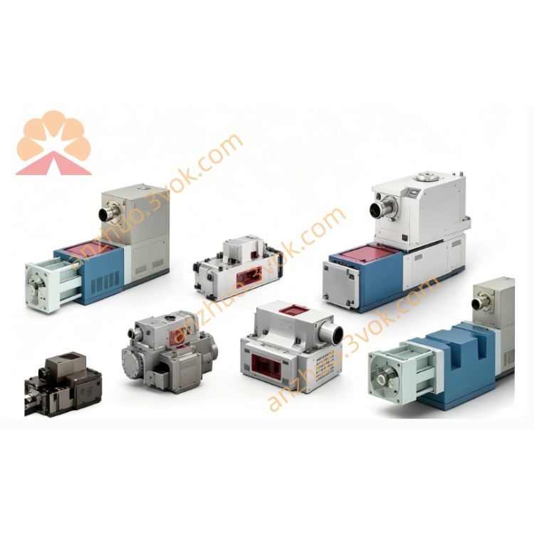
MOOG D633-7235 Direct Drive Servo Valve
Description
1. General Information
1.1 Intended Use
This manual covers the Moog D633-525B direct-drive servovalve (DDV), a high-precision electrohydraulic control unit for industrial hydraulic systems. It is designed for 4-way/3-way directional, velocity, pressure, and force control with mineral oil-based hydraulic fluids (DIN 51524).
1.2 Safety Symbols
⚠️ Warning: Risk of injury or equipment damage.
⚠️ Caution: Risk of equipment damage.
ℹ️ Note: Important operational information.
1.3 Qualified Personnel
Installation, operation, and maintenance must be performed by trained electrohydraulic technicians familiar with EN 982, DIN EN 50018/50019.
2. Product Description
2.1 Overview
The D633-525B is a size 03 (NG6) direct-drive servovalve with integrated electronics, permanent magnet linear force motor, and LVDT closed-loop spool position control for high accuracy and dynamic response.
2.2 Type Designation (D633-525B)
D633: Series (direct-drive, size 03)
525: Flow/pressure/configuration code
B: Seal/connector variant (HNBR seals, M12 connector)
2.3 Technical Specifications
2.3.1 Hydraulic Data
Mounting: ISO 4401-03-03-0-94穆格中国
Rated Flow: 40 L/min (Δp=35 bar per land, ±10%)穆格中国
Max Pressure: P/A/B=350 bar; T=50 bar (350 bar with Y port)Moog Inc.
Fluid: Mineral oil, ISO 4406 15/12 or better
Viscosity: 5–400 mm²/s (15–100 mm²/s recommended)
2.3.2 Electrical Data
Supply: 24 VDC (19–32 VDC)Moog Inc.
Current: ≤1.2 A
Command (Differential): ±10 V (10 kΩ) / ±10 mA / 4–20 mAMoog Inc.
Feedback: 4–20 mA (spool pos; 12 mA=centered)
Connector: M12 (5-pin), IP67
2.3.3 Environmental & Mechanical
Ambient Temp: -20 °C to +60 °C
Fluid Temp: -20 °C to +70 °C
Vibration: 30 g (3-axis)
Mass: 2.5 kg
3. Installation
3.1 Mounting Surface
Flatness: 0.01 mm/100 mm
Roughness: Ra < 0.8 µm
Cleanliness: No debris, burrs, or old sealant
3.2 Mounting Procedure
Remove port/mounting protective covers.
Align with ISO 4401-03 pattern; seat O-rings properly穆格中国。
Use M5×55 (10.9 grade) bolts; tighten diagonally to 6.8 Nm ±10%.
Check for port misalignment or O-ring extrusion.
3.3 Electrical Connection
3.3.1 M12 Pinout
表格
| Pin | Function |
|---|---|
| 1 | +24 VDC |
| 2 | 0 VDC (GND) |
| 3 | Signal GND |
| 4 | Command (+) |
| 5 | Command (−) / Feedback |
3.3.2 Wiring
Cable: Shielded, ≥0.75 mm²; shield grounded at supply end only。
Separation: ≥30 cm from high-voltage lines.
Torque: M12 connector to 2.5 Nm; verify IP67 seal.
4. Start-Up
4.1 Pre-Start Checks
System cleanliness: ISO 4406 15/12+。
Secure, insulated electrical connections.
No physical damage (dents, cracked housing).
Correct fluid level; 10 µm high-pressure filters (β₁₀≥75)。
4.2 System Flushing
Replace valve with flushing plate/valve。
Flush at operating temp until 15/12 cleanliness achieved。
Reinstall servovalve; replace flushing elements with high-pressure filters。
4.3 Initial Operation
Power 24 VDC; LED: green=normal, red=fault.
0 V command → spool centered (feedback=12 mA).
Gradually apply ±10 V; monitor movement/response.
Check for external leaks (mount, ports, connector).
Vent air to avoid “diesel effect” damage。
5. Operation
5.1 Normal Operation
Command: 0–±10 VDC / 4–20 mA → proportional spool positionMoog Inc.。
Feedback: 4–20 mA real-time spool monitoring (12 mA=center).
Fail-Safe: Power loss → spring-centered (neutral)。
5.2 Operating Limits
Max Pressure: P/A/B ≤350 bar; T ≤50 bar (350 bar with Y)Moog Inc.。
Temp: Avoid >10 °C fluctuations.
Fluid: No contamination (spool/bushing wear risk)。
6. Maintenance
6.1 Routine
Daily: Visual leak/cable/connector check.
Monthly: Filter pressure drop; replace if clogged.
Quarterly: Electrical connections/shield integrity.
Annual: Recalibrate spool position feedback (Moog procedure).
6.2 Cleaning
External: Lint-free cloths, non-abrasive cleaners.
No Solvents: On seals/connectors (damage risk).
Ports: Keep covered when unused.
6.3 Seal Replacement
Interval: Every 2 years or if leaks occur.
Seals: Moog OEM HNBR (P/N C55856-001).
Reassemble: Follow Section 3.2 torque specs.
7. Troubleshooting
7.1 No Hydraulic Response
Causes: No 24 V; bad command signal; spool jammed; clogged ports.
Remedies: Check power; verify wiring; clean spool/ports; replace filters。
7.2 Unstable Operation (Oscillation)
Causes: Resonance; low damping; contaminated fluid; misaligned spool.
Remedies: Adjust gains; check fluid; recalibrate spool; verify mounting flatness。
7.3 External Leaks
Causes: Loose bolts; damaged O-rings; cracked housing.
Remedies: Retorque to 6.8 Nm; replace O-rings; contact Moog for housing service.
7.4 Electrical Faults (Red LED)
Causes: Overvoltage; short circuit; faulty LVDT; bad electronics.
Remedies: Check voltage; inspect wiring; contact Moog for electronics repair.
8. Storage & Transportation
8.1 Storage
Environment: Clean, dry; -20 °C to +60 °C; humidity <60%.
Protection: Ports capped; original packaging preferred.
Max Storage: 5 years without inspection (contact Moog).
8.2 Transportation
Packaging: Shock-absorbent; avoid vibration/impact.
Orientation: Upright; no extreme temps.
Label: “Fragile – Precision Instrument”.
9. Warranty & Support
9.1 Warranty
12-month warranty from purchase date (materials/workmanship). Void if:
Unauthorized modification/repair.
Misuse, contaminated fluid, or bad installation。
Altered/removed serial number.
9.2 Support
Website: www.moog.com
Email: industrial.service@moog.com
Phone: +1-716-652-2000 (US); +49-89-99616-0 (Europe)
10. Declaration of Conformity
Moog GmbH declares D633-525B complies with:
Machinery Directive: 2006/42/EC
EMC Directive: 2014/30/EU
RoHS Directive: 2011/65/EU
Hydraulic Safety: EN 982, ISO 4401穆格中国
Electrical Safety: DIN EN 50018, DIN EN 50019
Get a Quote