
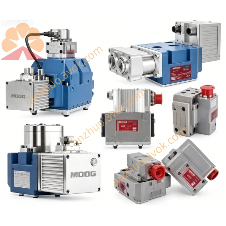
MOOG D633-498B Direct Drive Servo Valve
The D633-498B is a high‑performance single‑stage electrohydraulic direct drive servo valve (DDV) in the MOOG D633 series, featuring integrated closed‑loop electronics for precise spool position control. It uses a permanent magnet linear force motor to drive the spool directly, eliminating the need for external pilot oil supply. Designed for high‑dynamic response in electrohydraulic position, velocity, pressure or force control systems, it provides low hysteresis, high repeatability and compact construction. The valve is suitable for 4‑way, 3‑way and 2×2‑way flow control applications.
Description
1. General Description
The D633-498B is a high‑performance single‑stage electrohydraulic direct drive servo valve (DDV) in the MOOG D633 series, featuring integrated closed‑loop electronics for precise spool position control. It uses a permanent magnet linear force motor to drive the spool directly, eliminating the need for external pilot oil supply. Designed for high‑dynamic response in electrohydraulic position, velocity, pressure or force control systems, it provides low hysteresis, high repeatability and compact construction. The valve is suitable for 4‑way, 3‑way and 2×2‑way flow control applications.
2. Technical Specifications
2.1 Hydraulic Parameters
Rated flow is 280 L/min at 210 bar (3000 psi) pressure drop; refer to the official flow curve for exact values. Maximum operating pressure for ports P, A, B is 350 bar (5000 psi)Moog Inc.. Port T without Y drain is 50 bar (725 psi), and port T with Y drain is 350 bar (5000 psi)Moog Inc.. Compatible fluids are mineral oil‑based hydraulic fluids conforming to DIN 51524 parts 1–3. Recommended fluid viscosity ranges from 15 to 100 mm²/s, allowable viscosity ranges from 5 to 400 mm²/s. Fluid cleanliness requirement is NAS 1638 Class 6 or ISO 4406 15/12 or better. Neutral position leakage is less than 3.2 L/min. Step response time for 0–100% stroke is 12 msMoog Inc..
2.2 Electrical Parameters
Supply voltage is 24 VDC with acceptable range 18–32 VDCMoog Inc.. Maximum current consumption is 2.2 A. Input command signals include voltage mode 0 to ±10 VDC with 50 kΩ input resistance, current mode 0 to ±10 mA with 200 Ω load resistance, and 4 to 20 mA with 200 Ω load resistanceMoog Inc.. Spool position feedback signal is 4–20 mA with 300–500 Ω load resistance. Protection class is IP65 when mounted with mating connector. EMC compliance meets EC Directive requirements and relevant industrial standards.
2.3 Mechanical and Environmental
Mounting pattern conforms to ISO 4401‑03‑03‑0‑05. Weight is approximately 3.3 kg. Ambient temperature range is -20 °C to +60 °C (-4 °F to +140 °F). Fluid temperature range is -20 °C to +80 °C (-4 °F to +176 °F). Vibration resistance is 30 g, 3‑axis, 10 Hz–2 kHz. Shock resistance is 50 g, 6 directions, 3 ms. Standard seal material is NBR, FPM is optional for high‑temperature or special fluid applications.
3. Operation Principle
The D633-498B employs a permanent magnet linear force motor to directly drive the control spool. An electrical command signal (voltage or current) is converted to PWM current by the integrated electronics, driving the motor to move the spool bidirectionally from its spring‑centered position. An integrated LVDT sensor continuously measures the actual spool position and feeds the signal back to the internal controller. The electronics compare the command setpoint and feedback actual signals, adjusting the motor current in real time until the spool reaches the desired position, ensuring precise closed‑loop control. In case of power failure or cable breakage, the centering springs return the spool to neutral position, ensuring safe system shutdown.
4. Installation Instructions
4.1 Mechanical Installation
Ensure mounting surface flatness is ≤0.02 mm/100 mm and surface roughness Ra <1 μm. Use M5×60 DIN 912 bolts of 10.9/12.9 grade, tighten to torque 8.5–10 N·m. Align port P (inlet), T (return), A/B (actuator ports) and Y (drain) correctly, replace O‑rings if damaged to prevent leakage. The valve can be installed in any orientation; ensure drain port Y is properly routed if used to avoid backpressure issues.
4.2 Electrical Wiring
The valve uses a 6+PE‑pin DIN 43563 metal housing connector with IP65 protection. Pin assignment is as follows: Pin A for 24 VDC power, Pin B for 0 V (ground), Pin C not used, Pin D for command signal (voltage/current), Pin E for inverted command (voltage/current), Pin F for spool position feedback (4–20 mA), PE for protective ground. Use twisted and shielded cables for all signal and power lines. Connect shield to 0 V at power supply side and to connector housing for EMC protection. Ensure proper grounding to avoid ground potential differences and electrical interference.
5. Commissioning and Adjustment
5.1 System Flushing
Flush the hydraulic system thoroughly before initial operation and after any system modifications. Replace the valve with a flushing plate, then flush the system at operating temperature. Minimum flushing time is calculated by formula t=5V/Q, where V is reservoir volume and Q is pump flow rate. Continue flushing until system cleanliness reaches ISO 4406 15/12 or better. After flushing, install high‑pressure filters with β10 ≥75 (10 μm absolute) and mount the valve.
5.2 Electrical Null Adjustment
Remove the pan head screw on the electronics housing to access the 4‑turn null potentiometer. Apply 0 command signal to the valve, then adjust the potentiometer slowly until flow null is achieved, meaning no flow between A/B ports and T port. Reinstall the screw securely after adjustment to maintain IP65 protection and prevent contamination.
6. Maintenance
The valve is maintenance‑free under normal operating conditions with clean fluid and correct pressure/temperature settings. Replace system filters regularly to maintain fluid cleanliness at ISO 4406 15/12 or better. Inspect seals, connectors and wiring periodically for signs of leakage, damage or corrosion. Do not disassemble the valve body; unauthorized disassembly or repair will void the warranty. Contact MOOG‑authorized service facilities for professional repair or overhaul if necessary.
7. Troubleshooting
No hydraulic response may be caused by missing 24 VDC supply, faulty wiring or clogged ports; check power supply, inspect wiring continuity and clean blocked ports accordingly. Poor response or accuracy can result from contaminated fluid or incorrect null adjustment; replace hydraulic fluid and filters, then readjust null position. System oscillation or instability may be due to unstable external control loop or faulty feedback signal; tune external control loop parameters and check feedback wiring connections. Leakage at mounting surface is usually caused by damaged O‑rings or loose bolts; replace O‑rings and retighten bolts to specified torque. Null drift often occurs due to temperature changes or fluid contamination; readjust null position and improve system filtration to reduce contamination impact.
8. Safety Precautions
Installation, adjustment and maintenance must be performed by trained personnel familiar with hydraulic and electrical systems. Depressurize the entire hydraulic system and disconnect electrical power before disassembly or maintenance work. Do not exceed maximum pressure ratings (350 bar for P/A/B ports) to prevent valve damage or personal injuryMoog Inc.. Use only MOOG‑approved spare parts and accessories for replacement. Ensure proper electrical grounding to prevent electrical shock hazards and EMC issues. Follow all local safety regulations and industrial standards when operating the valve。
Get a Quote