
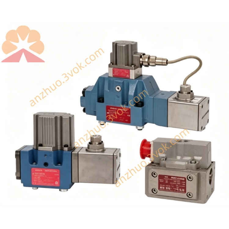
MOOG D633-473B Direct Drive Servo Valve
Description
1. General Description
2. Technical Specifications
2.1 Hydraulic Parameters
Rated Flow: 180 L/min (at 210 bar/3000 psi, refer to flow curve)
Max Operating Pressure:
Ports P, A, B: 350 bar (5000 psi)Moog Inc.
Port T (without Y): 50 bar (725 psi); (with Y): 350 bar (5000 psi)Moog Inc.
Fluid Compatibility: Mineral oil-based hydraulic fluids (DIN 51524 parts 1–3)
Fluid Viscosity: 15–100 mm²/s (recommended); 5–400 mm²/s (allowable)
Cleanliness Class: NAS 1638 Class 6 / ISO 4406 15/12 or better
Leakage: <2.0 L/min (neutral position)
Step Response Time (0–100%): 12 msMoog Inc.
2.2 Electrical Parameters
Supply Voltage: 24 VDC (18–32 VDC)Moog Inc.
Max Current Consumption: 1.5 A
Input Command Signals:
Voltage: 0 to ±10 VDC (input resistance 50 kΩ)Moog Inc.
Current: 0 to ±10 mA (load resistance 200 Ω); 4 to 20 mA (load resistance 200 Ω)Moog Inc.
Feedback Signal: 4–20 mA (spool position, load resistance 300–500 Ω)Moog Inc.
Protection Class: IP65 (with mating connector)Moog Inc.
EMC Compliance: Meets EC Directive requirements
2.3 Mechanical & Environmental
Mounting Pattern: ISO 4401-03-03-0-05
Weight: 2.7 kg (5.95 lb)
Temperature Range:
Ambient: -20 °C to +60 °C (-4 °F to +140 °F)
Fluid: -20 °C to +80 °C (-4 °F to +176 °F)
Vibration Resistance: 30 g, 3-axis, 10 Hz–2 kHzMoog Inc.
Shock Resistance: 50 g, 6 directions, 3 msMoog Inc.
Seal Material: NBR (standard), FPM (optional)
3. Operation Principle
4. Installation Instructions
4.1 Mechanical Installation
Mounting Surface: Ensure flatness ≤0.02 mm/100 mm and roughness Ra <1 μm.
Mounting Bolts: Use M5×60 DIN 912 (10.9/12.9 grade), torque to 8.5–10 N·m.
Port Connection: Align P (inlet), T (return), A/B (actuator ports), and Y (drain) ports; replace O-rings if damaged.
Installation Position: Any orientation (fixed or moving); ensure drain port Y is routed correctly if used.
4.2 Electrical Wiring
Connector: 6+PE-pin DIN 43563 (metal housing, IP65)Moog Inc..
Pin Assignment:
Pin A: 24 VDC Power
Pin B: 0 V (Ground)
Pin C: Not Used
Pin D: Command Signal (Voltage/Current)
Pin E: Inverted Command (Voltage/Current)
Pin F: Spool Position Feedback (4–20 mA)
PE: Protective Ground
Cabling: Use twisted, shielded cables; connect shield to 0 V (power supply side) and connector housing for EMC protection.
5. Commissioning & Adjustment
5.1 System Flushing
Flush the hydraulic system before initial operation and after modifications to achieve ISO 4406 15/12 cleanliness.
Replace the valve with a flushing plate; flush at operating temperature.
Minimum flushing time: (V=reservoir volume, Q=pump flow).
After flushing, install high-pressure filters (β10 ≥75, 10 μm absolute) and mount the valve.
5.2 Electrical Null Adjustment
Remove the pan head screw on the electronics housing to access the 4-turn null potentiometer.
With 0 command signal applied, adjust the potentiometer until flow null is achieved (no flow between A/B and T).
Reinstall the screw after adjustment to maintain IP65 protection.
6. Maintenance
The valve is maintenance-free under normal operating conditions (clean fluid, correct pressure/temperature).
Replace system filters regularly to maintain fluid cleanliness (ISO 4406 15/12 or better).
Inspect seals, connectors, and wiring periodically for leaks, damage, or corrosion.
Do not disassemble the valve; unauthorized repair voids the warranty. Contact MOOG-authorized service facilities for repair.
7. Troubleshooting
| Issue | Probable Cause | Remedy |
|---|---|---|
| No hydraulic response | No 24 VDC supply; faulty wiring; clogged ports | Check power supply; inspect wiring; clean ports |
| Poor response/accuracy | Contaminated fluid; incorrect null adjustment | Replace fluid/filters; readjust null |
| System oscillation | Unstable external control loop; faulty feedback | Tune external loop; check feedback wiring |
| Leakage at mounting | Damaged O-rings; loose mounting bolts | Replace O-rings; retighten bolts to torque |
| Null drift | Temperature change; fluid contamination | Readjust null; improve filtration |
8. Safety Precautions
Installation, adjustment, and maintenance must be performed by trained personnel familiar with hydraulic and electrical systems.
Depressurize the hydraulic system and disconnect electrical power before disassembly or maintenance.
Do not exceed maximum pressure ratings (350 bar for P/A/B) to prevent valve damage or personal injuryMoog Inc..
Use only MOOG-approved spare parts and accessories.
Ensure proper grounding to prevent electrical shock and EMC issues.
Get a Quote