
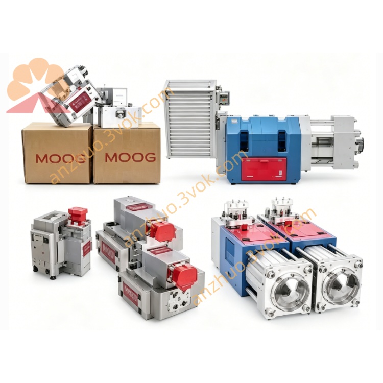
MOOG D633-473B Direct Drive Servo Valve
Description
1. General Description
2. Technical Specifications
2.1 Hydraulic Parameters
Rated Flow: 110–150 L/min (at 210 bar/3000 psi, refer to flow curve)
Max Operating Pressure:
Ports P, A, B: 350 bar (5000 psi)
Port T (without Y): 50 bar (725 psi); (with Y): 350 bar (5000 psi)
Fluid Compatibility: Mineral oil-based hydraulic fluids (DIN 51524 parts 1–3)
Fluid Viscosity: 15–45 mm²/s (recommended); 5–400 mm²/s (allowable)
Cleanliness Class: NAS 1638 Class 6 / ISO 4406 15/12 or better
Leakage: <1.5 L/min (neutral position)
2.2 Electrical Parameters
Supply Voltage: 24 VDC (22–28 VDC)
Max Current Consumption: 1.2 A
Input Command Signals:
Voltage: 0 to ±10 VDC (input resistance 50 kΩ)
Current: 0 to ±10 mA (load resistance 200 Ω); 4 to 20 mA (load resistance 200 Ω)
Feedback Signal: 4–20 mA (spool position, load resistance 300–500 Ω)
Protection Class: IP65 (with mating connector)
2.3 Mechanical & Environmental
Mounting Pattern: ISO 4401-03-03-0-05
Weight: 2.5 kg (5.51 lb)
Temperature Range:
Ambient: -20 °C to +60 °C (-4 °F to +140 °F)
Fluid: -20 °C to +80 °C (-4 °F to +176 °F)
Vibration Resistance: 30 g, 3-axis, 10 Hz–2 kHz
Shock Resistance: 50 g, 6 directions, 3 ms
3. Operation Principle
4. Installation Instructions
4.1 Mechanical Installation
Mounting Surface: Ensure flatness ≤0.02 mm/100 mm and roughness Ra <1 μm.
Mounting Bolts: Use M5×60 DIN 912 (10.9/12.9 grade), torque to 8.5–10 N·m.
Port Connection: Align P (inlet), T (return), A/B (actuator ports), and Y (drain) ports; replace O-rings if damaged.
Installation Position: Any orientation (fixed or moving).
4.2 Electrical Wiring
Connector: 6+PE-pin DIN 43563 (metal housing, IP65).
Pin Assignment:
Pin A: 24 VDC Power
Pin B: 0 V (Ground)
Pin C: Not Used
Pin D: Command Signal (Voltage/Current)
Pin E: Inverted Command (Voltage/Current)
Pin F: Spool Position Feedback (4–20 mA)
PE: Protective Ground
Cabling: Use twisted, shielded cables; connect shield to 0 V (power supply side) and connector housing for EMC.
5. Commissioning & Adjustment
5.1 System Flushing
Flush the hydraulic system before operation to achieve ISO 4406 15/12 cleanliness.
Flush with a flushing plate (replace valve) at operating temperature; minimum flushing time: (V=reservoir volume, Q=pump flow).
5.2 Electrical Null Adjustment
Remove the pan head screw on the electronics housing to access the 4-turn null potentiometer.
With 0 command signal, adjust the potentiometer until flow null is achieved (no flow between A/B and T).
Reinstall the screw after adjustment.
6. Maintenance
The valve is maintenance-free under normal operating conditions.
Replace system filters regularly (β10 ≥75, 10 μm absolute) to maintain fluid cleanliness.
Inspect seals and connectors periodically for leaks or damage.
7. Troubleshooting
| Issue | Probable Cause | Remedy |
|---|---|---|
| No hydraulic response | No supply voltage; faulty wiring; clogged ports | Check 24 VDC supply; inspect wiring; clean ports |
| Mounting surface leakage | Damaged O-rings; loose bolts | Replace O-rings; retighten bolts to specified torque |
| System instability/oscillation | Unstable external loop; faulty electronics | Check external control loop; return valve for repair |
| Null drift | Temperature change; contaminated fluid | Readjust null; replace fluid/filters |
8. Safety Precautions
Only trained personnel should install/repair the valve.
Depressurize the hydraulic system before disassembly.
Do not exceed maximum pressure ratings to prevent valve damage or injury.
Use only MOOG-authorized repair facilities; unauthorized repair voids the warranty.
Get a Quote