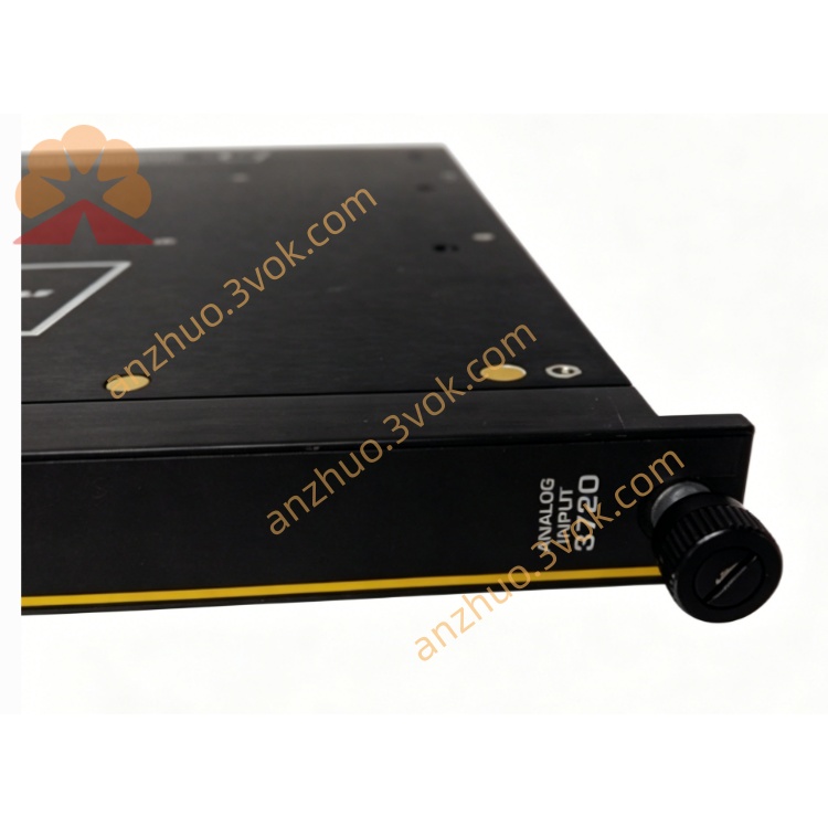
1. Product Introduction
TRICONEX 3720 is a high-density triple modular redundant analog input module belonging to the Tricon TMR safety instrument system series under Schneider Electric, specially developed for mass collection of DC voltage analog signals in SIL 3 critical safety control loops. It adopts full three-channel independent redundant sampling hardware architecture with two-out-of-three hardware voting mechanism, eliminating single-point signal acquisition failure risks in safety monitoring links.
This module carries 64 single-ended isolated analog input channels, dedicated to receiving 0–5VDC standard voltage signals from field transmitters, pressure sensors, temperature transducers and liquid level instruments. It integrates optoelectronic isolation circuits, full channel continuous self-diagnosis, over-range measurement function and online hot-swap capability. Different from low-density analog input modules such as 4409 for 4–20mA current signals, the 3720 features ultra-high channel density to save cabinet slot space for large-scale process plants with massive voltage-type field instruments. It runs 24/7 stably in wide-temperature, high-vibration and strong electromagnetic interference industrial environments, and single redundant sampling channel damage will not interrupt overall analog data collection and safety interlock logic execution. It is widely deployed in petrochemical refining, offshore oil & gas platforms, natural gas stations, thermal power boiler safety instrument systems and chemical production safety monitoring systems.
2. Model Definition Explanation
The complete model TRICONEX 3720 consists of brand identifier, core hardware classification code and optional configuration suffixes:
Prefix TRICONEX: Brand mark, representing Tricon TMR safety control hardware product line, separated from non-safety general control modules of other automation series.
Four-digit core number 3720: Internal rack analog I/O module classification coding. The first digit "3" stands for analog input/output functional category; the middle two digits "72" mark high-density multi-channel analog signal sampling circuit layout; the last digit "0" represents the base 64-channel single-ended 0–5VDC voltage input hardware platform, without built-in loop power supply for two-wire transmitters.
Optional suffix configuration codes attached after the model number to match differentiated project requirements:
No extra suffix: Standard indoor control room version, universal 0–5VDC single-ended input, suitable for non-hazardous cabinet installation.
-E: Full English firmware variant, all front panel fault codes, diagnostic prompts and TriStation configuration menu text displayed in English for overseas international projects.
-IS: Intrinsically safe matching variant with reinforced channel isolation barriers, applicable to Class I explosive hazardous area control cabinet deployment.
-HT: High-temperature extended operating variant, expanding stable upper operating temperature limit to +70°C for high-temperature workshop cabinets.
3. Technical Specifications
Electrical Performance
The module draws 24VDC operating power from the Tricon rack backplane, rated power consumption controlled below 7.5W, allowable input voltage fluctuation range 20VDC to 30VDC. Each of the 64 independent single-ended input channels accepts standard 0–5VDC voltage signals, supporting 6% extended over-range measurement to capture transient process over-limit values. Every channel adopts optoelectronic isolation with 2500VAC isolation withstand voltage between internal TMR sampling circuit and field sensor side. Input impedance of each channel reaches minimum 10MΩ DC, effectively reducing signal attenuation caused by long field wiring. Users can configure 12-bit or 14-bit analog-to-digital conversion resolution via TriStation software according to precision demands. Full 64-channel signal full-scan refresh cycle is controlled within 20ms, each sampling data frame carries millisecond timestamp to guarantee SOE accident recording accuracy. Each channel integrates independent overvoltage protection; overvoltage fault of a single channel only blocks signal collection of that channel and will not affect data acquisition of other channels and main system safety logic. The module does not provide built-in field loop power supply, external power distribution is required for field voltage output sensors.
Functional Safety & Reliability Index
TRICONEX 3720 fully complies with IEC 61508 SIL 3 and IEC 61511 process safety standards, and has passed UL, CE, ATEX and IECEx industrial safety certifications. Three internal redundant sampling circuits execute strict two-out-of-three hardware voting logic; distorted sampling data generated by any single redundant channel will be automatically filtered to avoid false safety interlock triggering caused by electromagnetic interference or single circuit damage. Hardware mean time to safe failure reaches 330,000 hours; mean time to repair is less than 10 minutes relying on online hot-swap function. It has complete single-fault masking capability; damage to one internal redundant circuit or fault of partial input channels will not cause overall signal collection failure of the module. All channel fault alarm records are latched and stored in non-volatile memory for long-term safety audit traceability.
Environmental & Mechanical Parameters
Standard model operating ambient temperature range covers -40°C to +65°C; HT high-temperature variant extends upper limit to +70°C. Spare module storage temperature range spans -40°C to +85°C, suitable for long-term warehouse storage. Tolerable relative humidity ranges from 5% to 95% without condensation. The module passes complete industrial EMC anti-interference tests including electrostatic discharge, radiated radio frequency interference, surge impact and fast transient pulse interference. It adopts standard single-slot horizontal installation matching Tricon safety I/O rack, no forced air cooling required under full rated load. Mechanical vibration resistance meets offshore oil platform, petrochemical plant and thermal power plant application standards; long-term low-frequency continuous vibration will not lead to sampling signal drift or channel misdiagnosis.
4. Interface and Communication Configuration
Hardware Interface Layout
The module integrates two independent hardware interface categories: rear internal backplane system interface and front field signal wiring interface.
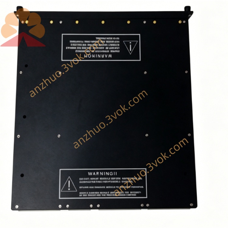
The rear gold finger dedicated connector is Tricon proprietary TMR backplane bus interface, responsible for redundant power supply access, three-way isolated bidirectional data exchange between the module and three redundant main CPU boards, and real-time uploading of hardware and channel fault codes to the rack mainframe.
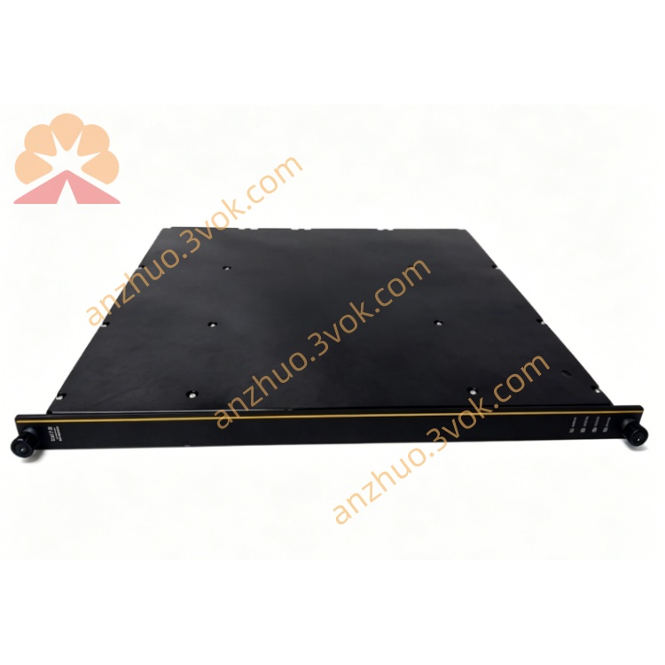
The front panel is equipped with dense screw-type terminal blocks corresponding to 64 input channels, independent shielding grounding terminals for each signal group, and multi-color LED diagnostic indicator lights. Indicators separately display module overall PASS normal running status, global hardware FAULT alarm, and group channel fault alarm lights, supporting fast on-site visual inspection of abnormal signal channels. All wiring terminals support compression connection of shielded twisted-pair industrial cables, convenient for centralized wiring of massive field voltage sensors.
Internal Backplane Communication Mechanism
Data interaction between TRICONEX 3720 and triple redundant main processors relies on three completely isolated proprietary high-speed backplane buses, corresponding one-to-one with the three internal sampling processing circuits of the module. Each redundant bus independently transmits real-time analog sampling values, channel range configuration parameters and loop fault diagnostic information from each CPU to the analog input module. Before uploading sampled data to main processors, the module executes two-out-of-three hardware voting on three groups of synchronous voltage sampling values to eliminate data inconsistency caused by single CPU or sampling circuit deviation. Faults such as backplane link disconnection, communication timeout and data parity errors will trigger the front panel red fault light and upload detailed fault location codes to TriStation configuration software and central HMI.
Input Channel Configuration Mode
The module does not carry independent Ethernet or serial communication ports; all channel signal range settings, resolution switching, engineering unit conversion formulas and fault threshold parameters are downloaded and stored in the redundant memory of Tricon main processors, and automatically synchronized to the 3720 module after power-on or hot-swap replacement. Users can independently set upper and lower safe limit values for each channel, configure alarm trigger points for over-range and under-range signals, and enable or disable open-circuit diagnosis function for each group of channels according to field sensor types.
5. Core Functions
Triple Redundant High-Density Voltage Signal Sampling
Three independent sampling circuits run synchronously to collect 0–5VDC voltage signals from up to 64 field sensors simultaneously, and upload verified valid sampling data to mainframe after passing two-out-of-three voting verification, avoiding abnormal safety judgment caused by single circuit signal distortion. Single channel wiring open circuit, short circuit or sensor failure only triggers local channel alarm and does not interfere with normal sampling of other safety monitoring channels, greatly improving cabinet space utilization compared with low-density analog input modules.
Full Channel Continuous Multi-Mode Self-Diagnosis
Continuous background diagnosis covers every input signal loop, capable of identifying multiple core fault modes: field wiring open circuit, signal over-range/under-range exceeding 0–5VDC nominal scope, channel internal isolation circuit breakdown and terminal block wiring looseness. All detected loop faults trigger the corresponding group red fault indicator alarm on the front panel, and upload fault channel number, occurrence timestamp and fault classification codes to the system central monitoring platform. Single channel loop fault will not shut down the overall sampling function of the module, and all fault records can be exported for factory safety compliance audit and accident root cause analysis.
Online Non-Stop Hot-Swap Maintenance
The module supports online plugging and replacement without cutting off the power supply of the entire safety rack. When pulling out a faulty 3720 module, the rack’s three redundant backplane bus architecture ensures that all safety analog signal collection logic of the system remains effective without interruption of process parameter monitoring. After inserting a spare module of the same model and locking front fastening screws, the Tricon mainframe automatically completes hardware identification, redundant channel synchronization and all channel configuration parameter copying within 30 seconds; all 64 input channels resume normal sampling and diagnosis functions without manual reconfiguration, eliminating production downtime caused by analog input module maintenance.
Multi-Layer Electrical Isolation and Anti-Interference Protection
Each input signal group is equipped with independent optoelectronic isolation barriers with 2500VAC isolation withstand voltage to limit cross-transmission of abnormal energy between field hazardous areas and internal TMR safety circuits, preventing lightning surges, static electricity and overvoltage from damaging core rack hardware. All field signal cable shielding layers must implement single-point grounding at the control room cabinet side to eliminate ground loop interference generated by long-distance wiring. Internal circuit partitioning separates each group of sampling channels to avoid mutual crosstalk and false over-range fault judgment caused by adjacent channel signal interference.
Configurable Sampling Precision and Over-Range Monitoring
Through TriStation configuration software, operators can switch 12-bit or 14-bit analog-to-digital conversion resolution for the whole module or single channels to balance system data storage load and measurement precision. Built-in 6% over-range detection function can capture transient peak voltage signals exceeding 5VDC, providing early warning for abnormal process surges that standard fixed-range modules cannot identify. Independent engineering unit conversion formulas can be set for each channel to convert raw 0–5VDC voltage values into physical process values such as pressure, temperature and liquid level directly displayed on HMI.
Batch Grouped Fault Visual Prompt
The front panel adopts grouped fault indicator design for 64 channels, instead of single-point independent lights, which reduces front panel layout complexity while enabling maintenance personnel to quickly locate which wiring terminal group has abnormal signals at the cabinet, improving daily inspection and troubleshooting efficiency for mass analog signal loops.
6. Applicable Scenarios
Large-Scale Petrochemical Refining ESD and Process Safety Monitoring Systems
Used as mass voltage signal collection module for crude oil distillation, catalytic cracking and hydrogenation unit safety racks, collecting voltage output signals from reactor temperature sensors, pipeline pressure transmitters and storage tank liquid level detectors, realizing centralized monitoring of hundreds of process safety parameters with minimal cabinet slot occupation.
Offshore Oil & Gas Platform Fire and Gas Protection Systems
Adapted to offshore high humidity, salt fog, vibration and strong electromagnetic interference environments, collecting voltage signals from wellhead pressure sensors, separator liquid level transmitters and combustible gas concentration detectors. The -IS intrinsically safe variant is adopted for control cabinets installed in Class I explosive hazardous areas on deck.
Natural Gas Transmission Pipeline Compressor and Storage Station Safety Systems
Serves station safety interlock racks, collecting voltage analog signals from pipeline pressure, flow and tank liquid level sensors distributed in wide-area valve groups, supporting unified over-limit safety alarm and emergency interlock trigger for dispersed pipeline process parameters.
Thermal Power Plant Boiler and Auxiliary Machine Safety Protection Systems
Applied in large boiler SIS racks, collecting voltage signals from furnace temperature sensors, steam pressure transmitters and drum water level detectors, supporting high-density real-time monitoring of boiler critical safety parameters and overtemperature/overpressure pre-alarm functions.
Large Fine Chemical and Pharmaceutical Multi-Workshop Safety Instrument Systems
Deployed in Class I explosive hazardous area control rooms with -IS intrinsically safe configuration, collecting reactor temperature, pressure and toxic gas concentration voltage signals from multiple production workshops, realizing centralized safety monitoring of multi-batch reaction equipment.
Coal Chemical and Hazardous Waste Incineration Plant Wide-Range Safety Monitoring
Suitable for production plants with large-area distributed storage tanks and incineration furnaces, collecting scattered tank liquid level, furnace temperature and flue gas pressure voltage signals, maintaining stable high-density sampling performance under high-dust and slightly corrosive field conditions.
7. Operation and Maintenance Instructions
Installation Requirements
TRICONEX 3720 must only be installed in dedicated analog input single slots of standard Tricon TMR safety I/O rack, inserted horizontally into the card slot, and front panel fastening screws must be fully locked to ensure reliable contact between the rear backplane gold finger connector and the rack bus. All field sensor signal cables must adopt double-shielded twisted-pair industrial cables; cable shielding layers must be single-point grounded at the control room cabinet ground bar, and multi-point grounding on field sensor equipment side is strictly prohibited to prevent ground loop induced interference. For intrinsically safe hazardous area cabinet installation, certified safety isolation barriers must be added between module front input terminals and field voltage sensors, strictly complying with intrinsic safety circuit parameter matching specifications. A ventilation gap of at least 15 centimeters must be reserved around the rack card slot; high-power heat-generating modules cannot be stacked beside the 3720 module to avoid overheating exceeding the rated operating temperature and triggering channel overvoltage protection faults. External 24VDC power supply must be configured separately for field 0–5VDC voltage output sensors, the module itself does not provide loop power supply.
Daily Routine Inspection Standards
Conduct daily visual inspection to confirm that the PASS indicator light on the front panel of the module remains steady green, the global FAULT alarm light is off, and no group channel fault alarm lights are illuminated. Log in to TriStation configuration software or system central HMI every day to check all 64 input channel sampling status, and confirm that there are no records of wiring open circuit, signal over-range, channel overvoltage or internal hardware faults. Every week, compare the voltage sampling value displayed by the module with the local reading of field sensors to judge abnormal signal attenuation or sampling drift. Every month, clean the dust accumulated on the front panel input terminals of the module and the ventilation slits of the rack, check the operating status of the cabinet cooling fan, and ensure that the ambient temperature around the module is maintained within the specified operating range of -40°C to +65°C.
Regular Inspection and Calibration Cycle
Under standard indoor control room operating conditions, full input channel sampling accuracy test and range calibration shall be carried out every 12 months; for offshore platforms, coastal salt fog workshops and high-temperature chemical production areas, the inspection cycle is shortened to 6 months. Before inspection, back up all channel resolution settings, range limits and engineering unit conversion parameters stored in the redundant memory of Tricon main processor. Use precision 0–5VDC signal generators to inject standard 0V, 2.5V and 5V calibration signals into each channel group one by one, verify sampling accuracy, adjust offset and gain compensation parameters in configuration software if measurement deviation exceeds standard tolerance. After completing all channel tests, save the updated configuration data to redundant system memory, and retain written inspection records including inspection date, operator name and fault test data for factory safety compliance audit.
Common Fault Handling Procedures
When a group channel fault alarm light is lit, first inspect the corresponding field sensor and signal wiring for breakage, short circuit or loose terminal joints, replace damaged sensors or rework wiring after eliminating external field equipment faults. If the global FAULT red light on the front panel is always on and multiple channel groups lose sampling capability simultaneously, check the 24VDC power supply voltage of the rack and whether the backplane connector has dust accumulation, corrosion or poor contact. If the system diagnosis displays internal sampling circuit hardware failure of the module, hot-swap maintenance can be performed directly without rack power-off: unlock front fastening screws, steadily pull out the faulty module, insert a spare TRICONEX 3720 module of the same suffix version, lock the screws tightly, wait for the automatic synchronization of channel configuration parameters to complete, then verify that all 64 input channels resume normal sampling and diagnosis functions and clear the historical fault alarm logs. On-site disassembly of internal circuit components of the module is forbidden; damaged modules must be returned to official authorized service centers for repair or scrapping. Unauthorized disassembly will invalidate all SIL3 safety certifications of the hardware.
Spare Module Storage and Long-Term Service Management
Offline spare TRICONEX 3720 modules shall be stored in a constant temperature dry warehouse with ambient temperature maintained at 0°C to 40°C and relative humidity controlled below 70%. The modules must be sealed in original anti-static packaging bags to prevent static electricity from damaging internal sampling and isolation chips, and avoid direct sunlight, corrosive gas and heavy dust accumulation environments. Every six months of shelf storage, take out the spare module for a 30-minute power-on aging test to activate internal circuit capacitors and prevent component performance degradation caused by long-term power-off state. The design service life of the module under rated normal operating conditions is 15 years; all on-site installed 3720 modules shall be replaced in batches when reaching the service life to maintain the overall SIL3 safety integrity level of the entire SIS system.
Maintenance Safety Prohibitions
Unauthorized modification of internal sampling chips, independent firmware burning or hardware wiring transformation of TRICONEX 3720 is strictly prohibited. Any modification will void functional safety certification and related industrial safety qualification certificates. Do not connect field signals with instantaneous voltage exceeding 6VDC to input terminals for a long time; continuous overvoltage will permanently burn internal optoelectronic isolation and sampling circuits. All maintenance operations involving module plugging, field signal cable replacement or channel range parameter modification must be operated by certified SIS safety instrument maintenance personnel. Safety isolation measures for production safety monitoring loops must be implemented before operation to avoid accidental triggering of emergency shutdown interlock logic during maintenance. Hot-swap replacement of the module is forbidden during critical production startup, shutdown or emergency accident handling stages; all module maintenance work must be arranged during planned equipment shutdown maintenance windows.
Get a Quote