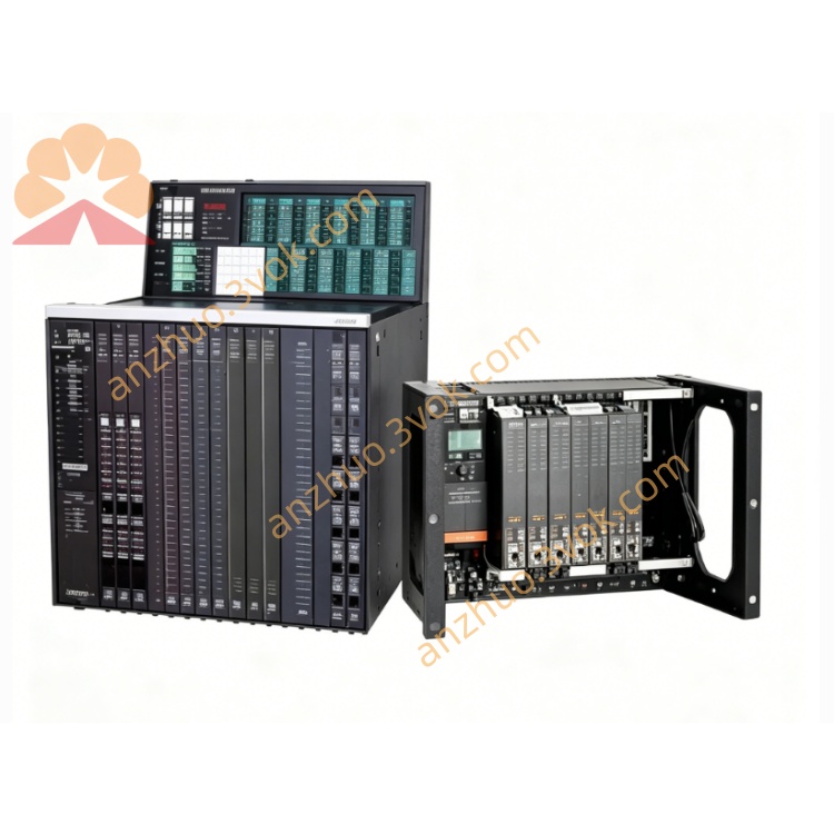
TRICONEX DO3401 triple modular redundant (TMR) non-supervised digital output module
Description
1. Product Overview
2. Model Naming & Matching Rules
TRICONEX: Brand of Tricon TMR safety control hardware
DO: Digital Output, discrete switching output module
3401: Hardware model code, 16-channel commoned non-isolated digital output card
Suffix variants
No suffix: Standard indoor cabinet general version
N (3401N): Enhanced EMC anti-interference variant for compressor islands and coastal plants
-E: English firmware version for overseas projects
-HT: High-temperature variant, max stable operating temperature up to +70°C for furnace-side cabinets
Supporting accessories
3. Core Electrical Specifications
Rack backplane power: 24VDC, power consumption ≤8W, operating voltage range 15~30VDC, absolute max transient voltage 33VDC
Channel configuration: 16 commoned digital output channels, non-galvanic isolation between internal TMR circuit and field side
Nominal output voltage: 24VDC
Single-channel electrical parameters
Typical continuous on-state current: 1.5A; self-limiting peak short-circuit current <4.8A
On-state voltage drop: <1.0VDC @1.5A load
Off-state leakage current to load: <1mA, avoids false lighting of low-power indicators
Reverse voltage withstand: -0.6VDC maximum reverse input protection
Scan & response performance
Full 16-channel loop-back scan cycle: <1ms
Output switching response delay: <2ms
Protection mechanism: Per-channel self-recovery overcurrent/short-circuit self-limiting protection; single-channel short only locks the corresponding channel without affecting other channels
No built-in loop supervision: Cannot detect load open-circuit, coil burnout or wire break faults (core difference from supervised DO series 3624/3725)
4. Functional Safety & Reliability Index
Safety certification: IEC 61508 SIL 3, IEC 61511, UL, CE, ATEX Zone 2 certified
TMR voting architecture: Three synchronous drive circuits execute hardware 2oo3 voting for all output commands; abnormal signals from any single channel are blocked to prevent accidental auxiliary equipment actuation
MTTFS (Mean Time To Safe Failure): 295,000 hours
MTTR: <10 minutes, supports non-stop online hot-swap maintenance
Single fault tolerance: Damage to one redundant drive channel only triggers FAULT alarm, the other two channels maintain normal 16-channel switching output
Fault logging: Backplane communication error, module hardware fault and channel overcurrent fault timestamps are latched in non-volatile memory for safety audit and troubleshooting
5. Environmental & Mechanical Parameters
Standard operating temperature: -40°C ~ +65°C; -HT variant extended to +70°C
Storage temperature: -40°C ~ +85°C
Relative humidity: 5% ~ 95% non-condensing, cabinet installation IP20 rating
EMC performance: Pass ESD, radiated RF, surge, fast transient burst interference tests; 3401N strengthens anti-salt-fog performance for coastal onshore plants
Installation: Single-slot horizontal plug-in in Tricon standard I/O rack
Cooling: Natural convection cooling, no forced fan required under full load
Vibration resistance: Compliant with onshore refinery, gas station and thermal power industrial vibration standards; not recommended for long-term offshore platform deployment due to lack of channel isolation
6. Hardware Interfaces & Front Panel Indicators
Front Panel LED Status Lights
PASS: Steady green = three redundant drive circuits run synchronously normally
FAULT: Red light = hardware failure, three-channel voting inconsistency or channel overcurrent protection trigger
CH1~CH16 ON/OFF independent indicators: Directly reflect real-time energized status of each field load
Hardware Interfaces
Rear gold finger connector: Proprietary Tricon TriBus triple redundant backplane bus, exchanges output commands and fault data with three main processors
Front wiring interface: Connect to matched FTA terminal base via ribbon cable for field 24VDC load wiring
Mechanical lock latch for fixing and hot-swap extraction
7. Core Key Functions
- TMR Triple-Redundant 16-Channel Auxiliary Digital Switching OutputThree independent drive circuits receive synchronous output commands from main processors, and only output 24VDC switching power after 2oo3 hardware voting verification. It is used for mass auxiliary signal distribution to save rack slots, and single-channel overcurrent fault will not interrupt other independent auxiliary loops.
- Per-Channel Self-Limiting Overcurrent & Short-Circuit ProtectionBuilt-in automatic current limiting circuit for each channel; when field wiring is short-circuited, the channel automatically limits output current to avoid module burnout, and resumes normal output after the short-circuit fault is eliminated without manual reset.
- Non-Stop Online Hot-Swap MaintenanceFaulty DO3401 can be replaced without shutting down the entire safety rack. After inserting a spare module, the three main processors automatically synchronize all channel fail-safe configuration parameters within 30 seconds without manual re-download, and auxiliary signal output remains uninterrupted during replacement.
- Configurable Fail-Safe State for Auxiliary LoadsVia TriStation software, users can set the safe state of each channel when communication or module fails: force OFF for alarm indicators, or hold ON for equipment running status holding relays, matching different auxiliary indication equipment requirements.
- Visual Channel Status Local IndicationIndependent ON/OFF LED for each of the 16 channels; maintenance staff can directly judge the energized state of on-site indicator lights and auxiliary relays at the cabinet without logging into HMI, improving daily inspection efficiency.
- High-Density Auxiliary Signal Centralized Distribution16-channel high-density design concentrates dozens of auxiliary status signals into one module, greatly reducing the number of occupied rack slots compared with low-channel supervised DO modules, suitable for large-scale auxiliary alarm and status display loops.
8. Typical Application Scenarios
Petrochemical refinery ESD auxiliary alarm light and interlock relay control
Onshore oil & gas station fire & gas pre-alarm indicator panel drive
Thermal power plant boiler auxiliary equipment running status signal output
Natural gas compressor station non-critical auxiliary valve position indication relay control
Medium-sized fine chemical workshop local emergency stop status display lights
SIS system renovation projects requiring large-capacity auxiliary discrete signal expansion
9. Installation & Maintenance Guidelines
Installation Restrictions
Compatibility: Only works with Tricon firmware V9.6 and above; cannot be matched with PI-series new-generation I/O hardware of V11+ platforms
Wiring specification: Field load cables adopt double-shielded twisted pair; all cable shields are single-point grounded at cabinet ground bar, double-end grounding is forbidden to avoid ground loop interference
Hazardous area deployment: When the FTA terminal base is installed in Zone 2 hazardous cabinets, matched certified safety isolation barriers must be added between field loads and terminals
Slot layout: Install in standard digital output dedicated slots of I/O rack; reserve at least 15cm ventilation gap around the module to prevent overheating
Daily Inspection Standards
Visual check: PASS light steady green, no constant FAULT red light; each channel LED matches the actual field load state
Weekly operation: Log into TriStation to export module overcurrent fault logs
Monthly maintenance: Clean dust on front panel indicators and FTA terminal blocks, check cabinet cooling fan and ambient temperature
Regular Inspection Cycle
Standard indoor control room: Full channel output function test every 12 months
Coastal salt-fog / high-temperature furnace-side cabinets: Inspection cycle shortened to 6 months
Test items: Channel short-circuit protection function verification, fail-safe state switching test
Common Fault Handling Steps
Single channel LED off but no FAULT alarm: Check field load power supply, wiring open circuit or relay coil burnout; this module cannot detect load loss due to lack of supervision function
Single channel triggers FAULT light: Inspect field wiring short-circuit fault, clear the short and the channel will automatically recover
Global FAULT light permanently lit: Check rack 24VDC backplane power supply, re-lock module latch to ensure complete backplane contact
Internal hardware failure: Perform hot-swap replacement with identical spare DO3401, wait for automatic parameter synchronization then clear historical fault records
Prohibited Operations
Spare Module Storage & Service Life
Storage environment: Constant-temperature dry warehouse (0~40°C, RH ≤70%), sealed in original anti-static packaging bags to avoid static damage to internal circuits
Shelf maintenance: 30-minute power-on aging test every 6 months to activate internal circuit capacitors
Design service life: 15 years under rated operating conditions; batch replacement is recommended after expiration to guarantee overall SIS SIL safety integrity level
Get a Quote