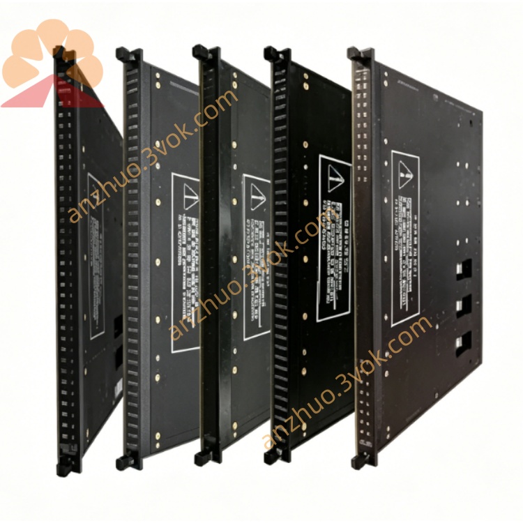
TRICONEX 9753-110 passive voltage input field termination panel
Description
I. Product Overview (Core Parameters)
1) Basic Specifications
Model: 9753-110 (Voltage Input, 0–5V/0–10V, Basic, 16 Points)
Signal Type: Analog Voltage Input (0–5VDC, 0–10VDC single-ended / differential)
Channels: 16 Points / Board; 32 Points AI Module requires 2 Boards
Input Range: 0–5VDC, 0–10VDC (Software Configurable)
Input Impedance: ≥1MΩ (High Impedance, Suitable for Voltage Sensors)
Isolation: ≥1500VAC Field - System Isolation, Channel-to-Channel Isolation
Accuracy: ±0.1% FS @ 25℃
Resolution: 16 Bit
Diagnosis: Open Circuit / Short Circuit Detection, TMR Triple Redundancy
Safety Level: SIL3 (IEC 61508)
Operating Voltage: 24VDC ±10% (Terminal Board Power Supply)
Power Consumption: <5mW / Channel
Temperature: –40℃ ~ +70℃
Certifications: CE, UL, CSA, ATEX/IECEx
Installation: 35mm DIN Rail
Compatible Modules: 3503, 3700A (Tricon 32 Point Voltage Input Module)
Connection Cable: Special Flat Cable (e.g. 9753-110 Packed Cable)
2) Panel and Indicator Lights
CH01–CH16 (Green): Lit when channel signal is normal
PWR (Green): 24VDC Power Supply is Normal
FAULT (Red): Channel Fault (Open Circuit / Short Circuit / Overrange)
3) Comparison of the Same Series (9753 vs 9750)
9753-110: 16 Point 0–5V/0–10V Voltage Input (Basic Type)
9750-810: 32 Point 0–5V/0–10V Voltage Input (Basic Type)
9764-310: General Terminal Board for RTD/TC/AI (With Cold Junction Compensation)
II. Operating Instructions (Installation / Wiring / Maintenance)
1) Installation Configuration
32 Point AI Module (3503/3700A): 1 Module paired with 2 9753-110 (1–16, 17–32)
Installation Location: Cabinet DIN Rail, Close to the Field Sensor to Reduce Signal Interference
Hot Swap: Supports Online Replacement without Affecting System Operation
2) Wiring Specifications (Voltage Signal)
Single-ended Input: CH+ → Signal +; CH‑ → Signal - / Ground
Differential Input: CH+ → Signal +; CH‑ → Signal - (More Anti-Interference)
Wire Diameter: 1.0–1.5 mm² Shielded Twisted Pair, Single-ended Grounding of Shield Layer
Range: Software Configurable Select 0–5V or 0–10V, Matching Sensor Output
3) Fault Handling
FAULT Lit: Open Circuit / Short Circuit / Overrange of Channel → Check Sensor Wiring, Power Supply, Range Matching
CH Unlit: Check 24VDC Power Supply, Flat Cable Connection, Module Configuration
PWR Unlit: Check 24VDC Power Supply, Terminal Board Fuse
Get a Quote