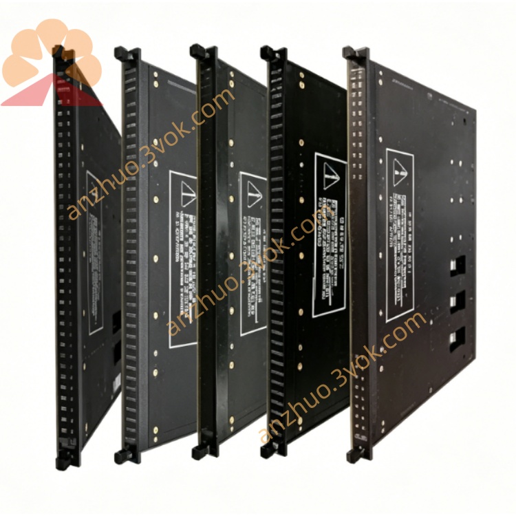
TRICONEX 8111 high-performance TMR triple modular redundant main processor module
Description
I. Product Overview (Core Parameters)
1) Basic Specifications
Model: 8111 (Local Expansion Chassis)
Architecture: TMR Triple Redundancy (Backplane / Bus / Power Triple Redundancy)
Slots: 12 I/O slots (Full-length cards, same as 8110)
Controller: No CPU (Must be controlled by 3008 CPU of 8110 mainframe)
Power Supply: Dual redundant 24VDC (8300×2, hot standby, replaceable online)
Expansion Bus: 6×RS-485 (Triple Redundant Bus, connected to 8110 or other 8111)
Dimensions (mm): 483×445×333 (Same as 8110, 19" standard chassis)
Weight: 24.5 kg
Temperature: -40℃ ~ +70℃ (Industrial wide temperature)
Certifications: CE, UL, CSA, SIL3, ATEX
2) Core Differences from 8110 Mainframe (Easy to Distinguish at a Glance)
8110 (Mainframe): 3×3008 CPUs + 2×8300 Power Supplies, System Core, Must 1
8111 (Expansion Chassis): No CPU, Only 2×8300 Power Supplies, Pure I/O Expansion, Can Multiple
Key Switch: 8111 has no front panel key switch (System Start/Stop Controlled by 8110)
Quantity: 1 8110 Can Support Up to 14 8111/8112 Expansion Chassis
3) Modules that Can Be Installed (Same as 8110)
I/O Modules: 4000 Series DI/DO, 3700 Series AI/AO
Communication Cards: 4315B, 4351A (TCM, connected to DCS/Third Party)
FTA Base: 7400206-100 (CM2201, Slot Backplane), 7400213-100 (Field Wiring)
Not Installable: 3008 CPU (Can Only Be Installed in 8110)
II. Usage Instructions (Installation / Wiring / Configuration)
1) Rack Installation (19" Cabinet)
Location: Below/above the 8110 mainframe in the cabinet, for easy connection of bus cables
Fixation: 4 Cabinet Screws for fixation, reliable connection to cabinet ground (Anti-interference)
Stacking: Up to 4 Chassis Stacked (8110 + 3×8111), Leave Space for Heat Dissipation
2) Module Installation (From Left to Right)
Slot 1–2: Power 8300×2 (Dual Redundancy, Must Install)
Slot 3–12: I/O/Communication Modules (4000/3700/43xx Series, 10 Slots)
Base: Insert 7400206-100 Backplane Base under the Module
FTA: Install 7400213-100 Wiring Base at the Back of the Cabinet, Connect to Field Cables
Hot Swap: All I/O/Communication Cards, Power Supports Online Replacement, No Shutdown Required
3) Expansion Bus Connection (Critical!)
Cables: Special Triple RS-485 Expansion Cables (Tricon Bus Cables)
Interfaces: 6 RS-485 Ports on 8110 Backplane → Connect to 8111 Backplane RS-485 Ports
Topology: Daisy Chain (8110 → 8111 → 8111…), Up to 14
Distance: Local Expansion ≤ 30 meters (Cable); Remote Use 8112 Optical Chassis (12 kilometers)
Terminal Resistor: Connect Terminal Resistor to the Last 8111 Bus Port (Prevent Signal Reflection)
4) TriStation Configuration
Automatic Identification: TriStation Automatically Identifies 8111 and All Modules upon Power On
Chassis Address: 8110 = Chassis 0; 8111 is sequentially set as Rack 1, 2, 3...
Redundancy configuration: TMR triple redundancy, dual power supply redundancy is enabled by default
Program download: Press the key switch on 8110 to switch to PROGRAM and download the program; complete the switch to RUN
5) Indicator lights and diagnostics
PASS (green): Rack is normal and communicates synchronously with 8110
FAULT (red): Power / bus / module failure, TriStation locates to the specific slot
ACTIVE (yellow): I/O communication is active
Common faults:
FAULT is on: Mostly due to loose / damaged extension cables, missing terminal resistors, or power failure
No communication: Check the bus cables, connectors, and rack address settings
6) Daily maintenance
Regular checks: Fasten screws, module locks, grounding, bus cable connectors
Cleaning: Clear dust after power off, keep the air ducts unobstructed
Spares: Keep 8300 power supply and common I/O modules on hand, replace quickly by hot-plugging in case of failure
Get a Quote