
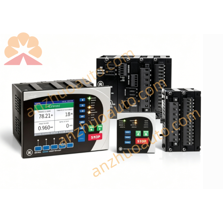
GE 137D6751G1
Description
GE 137D6751G1, also marked with identifier 1L2‑B005 and labelled SPFB TC/SPF CVT, is an original‑equipment interconnect printed‑circuit‑board spare hardware built for legacy GE gas‑turbine control‑rack signal‑interconnection applications in large‑scale power‑generation facilities. Every board unit undergoes circuit continuity inspection, relay component testing and full rack‑slot compatibility verification before factory shipment, ensuring complete electrical‑path interchangeability with the originally‑installed hardware during on‑site overhaul and spare‑part‑replacement maintenance work.
As an intermediate signal‑interconnection carrier inside the turbine‑control chassis, GE 137D6751G1 forms a vital signal‑transfer link between field‑mounted thermocouple temperature sensors and upstream signal‑conditioning or amplifier modules within the control rack. Raw thermocouple feedback signals from turbine‑hot‑gas‑path and casing temperature sensors are routed to the edge‑connector terminals on this board. Its internal copper traces, onboard sealed relay unit and dedicated test‑point (TP1) terminal provide configurable signal‑routing channels for temperature‑measurement loops, allowing maintenance technicians to carry out convenient on‑site signal‑sampling, continuity‑check and troubleshooting work without disconnecting upstream wiring. Built‑in surge‑suppression components filter transient electrical noise picked up along long field sensor cables, reducing signal distortion and protecting subsequent signal‑processing hardware from voltage‑spike damage. Gold‑plated edge‑connectors at one end of the board minimize contact‑resistance drift and poor‑connection failure risks after years of continuous rack‑mounted service.
This interconnect‑circuit‑board module adopts a standard horizontal rack‑insertion installation form and fits into the dedicated designated slot of the GE turbine‑control chassis. Its hardware design is optimized for typical control‑room operating‑conditions, including moderate ambient‑temperature fluctuation, low‑level mechanical vibration and light dust accumulation. After long‑time continuous‑operation, onboard sealed‑relay contact degradation, copper‑trace corrosion, solder‑joint fatigue and gold‑plated‑connector oxidation are the most‑common failure modes. If the board suffers performance degradation or complete failure, partial or total loss of thermocouple temperature‑feedback signals will occur, resulting in incomplete turbine‑temperature monitoring data, false high‑temperature fault‑alarms or unexpected gas‑turbine shutdown, which may cause considerable economic losses to power‑generation facilities. Periodic inspection and timely renewal of ageing interconnect‑loop boards are essential elements of gas‑turbine preventive‑maintenance schedules.
During field‑replacement maintenance, technicians must strictly follow electrostatic‑discharge protection specifications to avoid static‑electricity damage to sensitive onboard relay components. Before inserting GE 137D6751G1 into the control rack, maintenance staff shall complete visual inspection, checking for transport‑related scratches, burnt traces, cracked traces or bent connector pins, and verify that the part‑number matches the original hardware specification. After rack installation, power‑off continuity‑loop testing, thermocouple‑signal path verification and closed‑loop sensor‑signal debugging must be carried out to confirm stable signal‑transmission performance between this interconnect board, upstream conditioning modules and the field‑side temperature‑sensor equipment. Successful board‑replacement quickly restores the complete thermocouple‑signal‑interconnection‑path function of the turbine‑control rack, shortens equipment‑downtime duration and cuts financial losses caused by unit shutdown.
GE 137D6751G1 is widely used for maintenance‑renewal projects in thermal‑power‑stations, combined‑cycle gas‑turbine plants and industrial captive‑power facilities equipped with GE legacy Speedtronic turbine‑control hardware. Unused spare circuit‑boards should remain sealed inside anti‑static packaging and be kept in dry, constant‑temperature warehouses, away from humid and corrosive environments that may cause circuit‑board trace corrosion and connector oxidation. Throughout installation, commissioning and fault‑diagnosis activities, maintenance personnel shall comply with industrial electrical‑safety regulations and follow GE’s official hardware‑maintenance manuals. Deploying genuine GE spare printed‑circuit boards such as 137D6751G1 ensures dependable thermocouple‑signal interconnection performance for gas‑turbine temperature‑monitoring‑systems, improves unit‑operation stability and optimizes the long‑term maintenance‑cost budget of power‑generation assets.
Get a Quote