
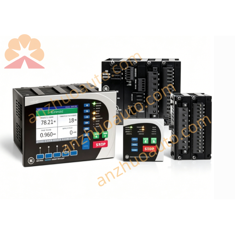
GE 12PVD21B2A
Description
GE 12PVD21B2A is a high‑performance high‑impedance differential‑voltage protective relay designed for critical bus‑bar differential‑protection applications within utility‑operated substations, thermal‑power‑generation stations and large‑scale industrial power‑distribution networksGE Vernova. Every unit undergoes precise mechanical assembly, voltage‑pickup calibration and comprehensive functional testing before factory shipment, ensuring fast, consistent tripping performance and full mechanical interchangeability with legacy PVD‑series hardware during on‑site overhaul and spare‑part‑replacement projects.
This relay adopts the well‑proven high‑impedance bus‑differential protection principle. All current transformers connected to every feeder circuit on the protected bus‑bar are wired in parallel across the relay input terminals. Under normal operating conditions or during external faults outside the protected bus zone, secondary currents from current transformers circulate between CT units, and almost no voltage appears across the relay terminals. The relay remains stable and will not trigger unwanted tripping, even if saturation occurs on one of the external‑fault‑side current transformers. When an internal short‑circuit fault takes place on the protected bus‑bar, unbalanced differential voltage is generated across the relay input. Once this voltage exceeds the preset pickup threshold, the high‑speed voltage‑sensing element (87L) actuates immediately and sends out a trip command to open all connected circuit breakers, quickly isolating the faulty bus‑bar section from the power‑grid. The typical operating speed reaches approximately 20 milliseconds at four‑times pickup voltage, minimizing equipment‑damage risks caused by high‑magnitude bus‑fault currentsGE Vernova.
As a PVD21B variant, GE 12PVD21B2A incorporates one Thyrite surge‑limiting stack to suppress dangerous over‑voltages developed across the relay terminals during heavy‑internal‑fault events, protecting internal components from voltage‑spike‑related damageGE Vernova. It also comes equipped with a separate high‑seismic instantaneous over‑current unit (87H) with independent output contacts. This auxiliary over‑current element can serve as supplementary backup protection for the main voltage‑sensing unit, or it may be configured for circuit‑breaker‑failure protection logic when coordinated with external timing and auxiliary relays. Dual‑element design greatly improves overall protection‑system security and fault‑detection reliability for vital bus‑bar assets.
The relay is housed inside a rugged draw‑out panel‑mount enclosure suitable for installation inside high‑voltage protection cabinets. Its reinforced mechanical construction features enhanced seismic‑resistance performance, enabling stable operation under vibration‑prone substation environmental conditions. Before field installation, maintenance technicians must complete a full visual inspection for transport‑induced damage on housing, wiring terminals and internal components. Engineers are required to perform CT‑circuit stability calculations, including knee‑point‑voltage verification for every connected current transformer. After differential‑loop wiring is finished, secondary‑voltage‑injection functional testing must be carried out to verify pickup‑voltage threshold, fast‑trip‑operating speed and contact‑switching reliability, confirming all parameters satisfy bus‑differential‑protection stability and sensitivity requirements.
GE 12PVD21B2A is widely selected during preventive‑maintenance overhaul, faulty bus‑protection‑relay renewal and substation‑bus‑protection‑system upgrade projects. Unused spare relays should be stored in dry, temperature‑controlled indoor warehouses, kept away from humid air and corrosive gas which may degrade Thyrite components or internal‑mechanical‑part performance. During installation, commissioning and periodic inspection, all high‑voltage electrical‑safety codes and GE’s official PVD‑series operation manuals must be strictly followed. Deploying genuine GE high‑impedance differential relays delivers ultra‑fast, stable bus‑bar fault protection, reduces severe‑fault‑related outage losses and improves the overall operational safety of substation power‑distribution facilities.
Get a Quote